
This blog explains how to adjust the valves on a Royal Enfield 650 Interceptor. This was the first valve adjustment my motorcycle has had, and it occurred at the 500-mile mark. The first valve adjustment is an important one, as decreases in the valve gap will typically be more severe as the engine is breaking in. For the record, though, on my bike’s eight valves only one was slightly tight (and that was one of the intake valves). The other seven were pretty much where they were supposed to be, but I loosened the adjusters and readjusted them just to see if any were difficult to access or if they would give me any problems. Accessibility was superb and the adjustments were all easy to make.
Like most threaded adjuster valve adjustments, 90% of the job is just taking away or loosening the stuff you need to get at the valves (and then putting it all back on the bike). On the Enfield, that’s the right side body panel, the seat, the fuel tank and its connections, an electrical subassembly between the upper frame rails, and the valve cover. The actual valve adjustment only takes a few minutes.
You’ll need several tools for this job. Here’s the list:
-
-
- Feeler gage.
- 17mm socket.
- 8mm socket.
- 10mm socket.
- Sparkplug socket.
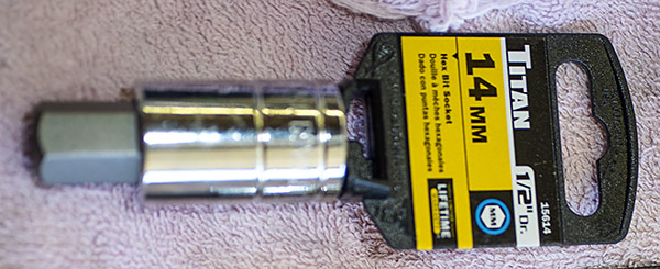
- 14mm Allen drive.
- 4mm Allen drive.
- Ratchet with extensions.
- 10mm wrench.
- Flat blade screwdriver.
-
Because I’m an old fart and a pack rat, I had everything I needed except for the 14mm Allen drive (that was one I had to order on Amazon). Odds are you already have most or all of this stuff already, too. We tend to pick up oddball stuff over the years. If you live on the Tinfiny Ranch, that includes stuff like lathes, concrete mixers, tillers, old MGs, and more. But the only tools you’ll need for adjusting the Enfield 650’s valves are what I listed above.
The other thing we need to do is make sure the engine is completely cool. You can’t ride the motorcycle, shut it off, and then adjust the valves. The engine needs to be cold.
Adjusting the valves sounds way more intimidating than it is. I took a couple of hours to adjust the valves on my Enfield and this was the first time I did it. On subsequent valve adjustments I’m guessing I’ll need less than an hour now that I know my way around the bike. Dealers charge up to $581 for this job, which is kind of a joke when you consider the amount of time it takes (that is, if you think getting ripped off by a dealer is funny). The dealers are counting on you being intimidated. You shouldn’t be. This is not a hard thing to do.
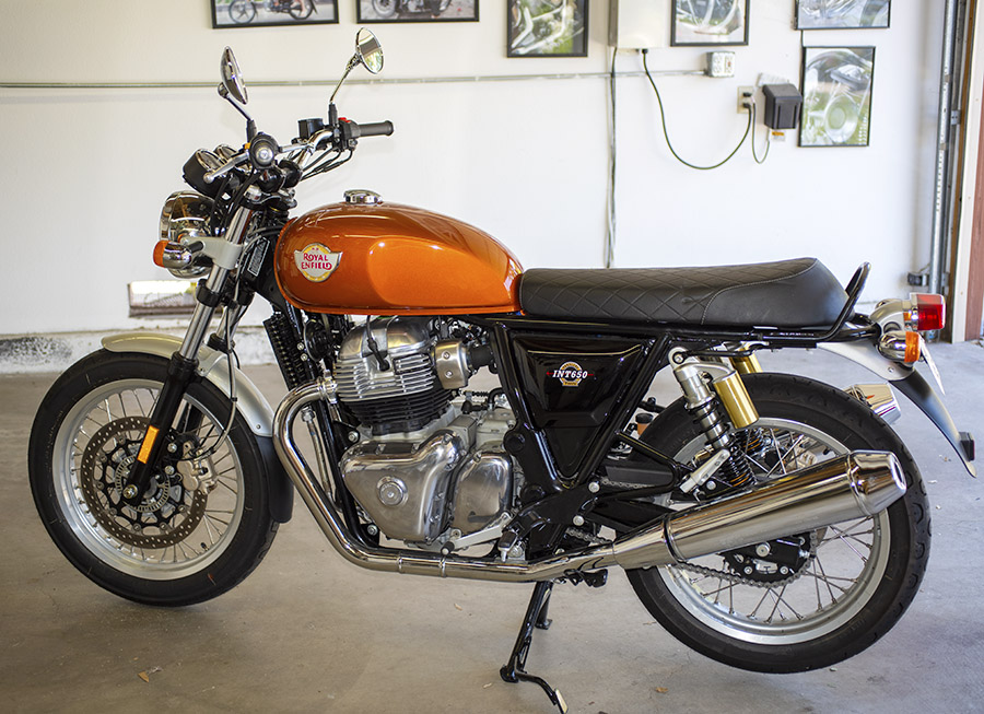
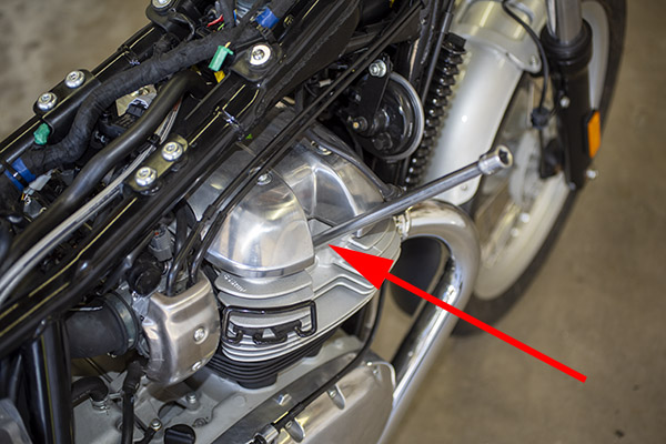
Start by putting your motorcycle on the center stand, as you see in the big photo at the top of this blog. That makes getting to both the left side and the right side of the bike easier.
Use your ignition key to unlock the right side body panel. It pivots out from the bottom and then pulls down, and that will take it off the bike.
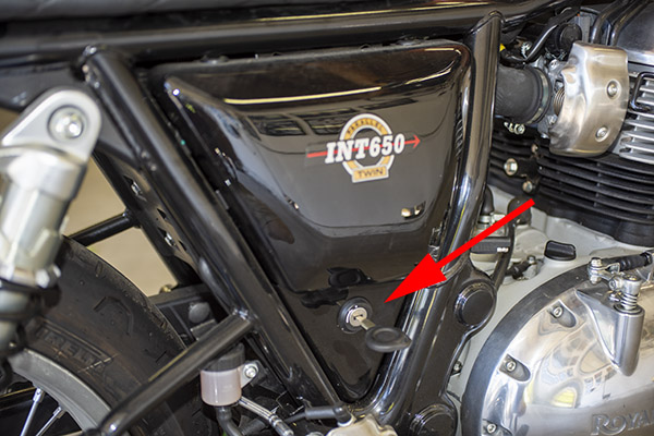
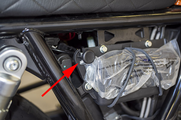
Once the right side body panel has been removed, you’ll have access to the seat release (shown by the red arrow). Pull it out and remove the motorcycle seat by sliding the seat to the rear.
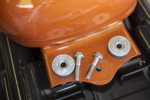
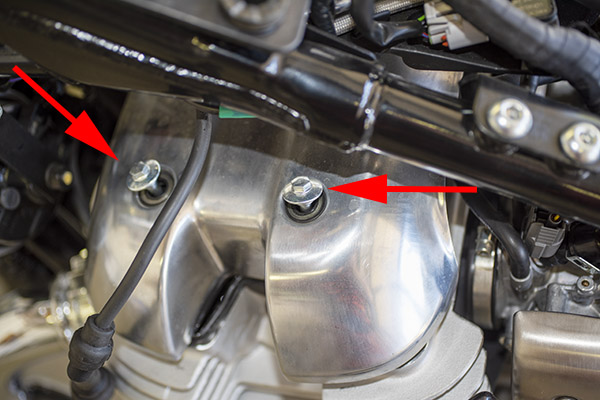
The next step is to remove the two 10mm bolts securing the fuel tank to the frame. This job is a lot easier if you run the fuel level down (it makes the tank lighter and easier to handle when you disconnect the two electrical connections and the three hoses underneath the tank). I had mine on E, but there was still a fair amount of fuel in the tank.
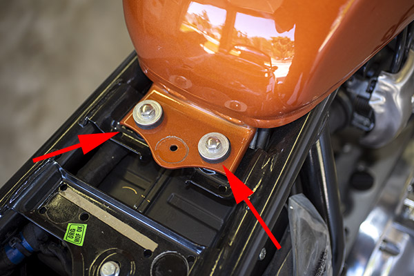

Once the two bolts are removed, set them aside (not like you see here; put them someplace where you won’t lose them). The tank will then slide to the rear. Put a shop rag on the frame behind the tank so you won’t scratch anything.
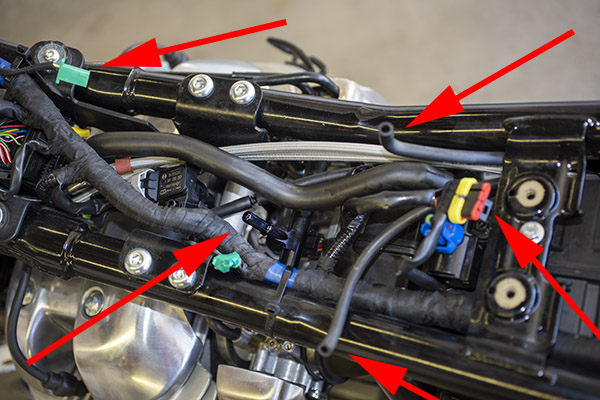
As mentioned above, there are five things that have to be disconnected underneath the fuel tank so that you can remove it from the motorcycle. As seen in the photo below, going counterclockwise from the upper left corner of the photo, these five things are:
-
-
- An electrical connector to the fuel gage (the green connector).
- A fuel vent line.
- The fuel pump electrical connector (the yellow, red, and black connector).
- Another fuel tank vent line.
- The fuel hose (this is mated with a quick-disconnect fitting that stays on the fuel tank; it has a button you press to allow pulling the fuel hose off).
-
I show this on the motorcycle side of the equation. It would have been a little tough to get a photo of the bottom of the tank.
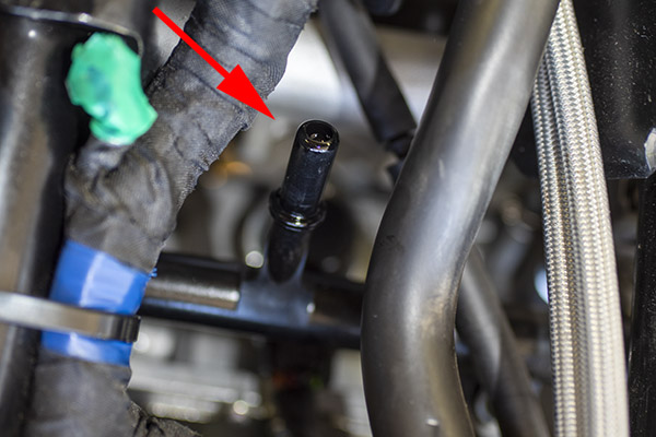
Here’s another shot of the fuel hose quick disconnect male end (it stays with the motorcycle).
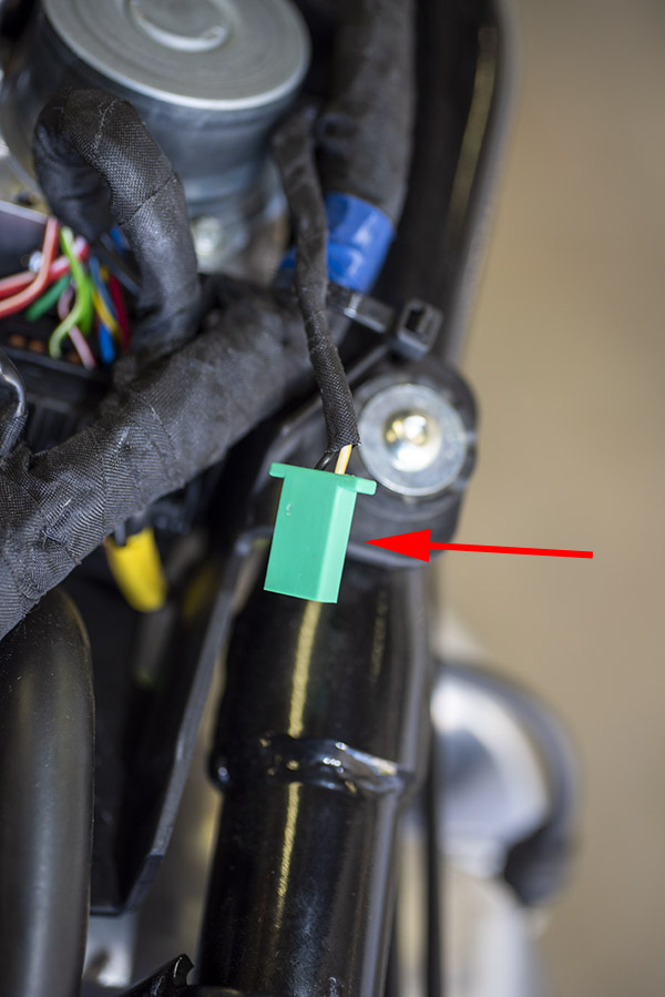
This is another shot of the fuel level gage electrical connector.
And here’s a photo of one of the fuel vent lines and the fuel pump electrical connector.

After tilting the tank up and disconnecting all five of the connections described above, remove the tank and place it on a cloth to prevent scratching.
At this point, disconnect the sparkplug leads and remove both sparkplugs. We are going to crank the engine by hand, and we don’t want to have to fight the engine’s compression as we do so.
The next step is to remove the three Allen bolts that secure an electrical subassembly between the upper frame rails. We don’t need to remove the subassembly; we just need it to be pushed up so that we can maneuver the valve cover out of the way (which, incidentally, I found to be the hardest part of the valve cover adjustment process). Set the three Allen bolts aside in a secure location.

Next, remove the four 8mm bolts securing the valve cover. Set them aside in a secure location.
Once the four valve cover bolts are out, you can remove the valve cover. It will slide out on the left side of the motorcycle. You’ll probably invent a few cuss words when doing this. The valve cover is a tight fit between the cylinder head and the motorcycle frame’s upper rails (it’s why we loosened that electrical subassembly described above). There’s a complicated and reuseable rubber gasket that seals the valve cover to the cylinder head. Be careful not to nick the gasket when you’re sweet-talking the valve cover off the engine.
Once the valve cover is off the engine, you’ll have access to the valve adjusters. As this is an eight-valve engine, there are four adjusters for each cylinder (two intake and two exhaust valves). The four valves on the right side of the engine are shown below.

And these are the four valves on the left side of the motorcycle.

Here’s where you’ll need that 14mm Allen drive mentioned above. It was the only tool I didn’t already have. It was something like $6 on Amazon, and I now have two of them. Amazon sent me an email a couple of days after I ordered the tool because they felt like they lost one in shipment so they shipped it again, and then two arrived in separate packages on the same day. Don’t tell Amazon. I’m keeping both. Bezos can afford it.
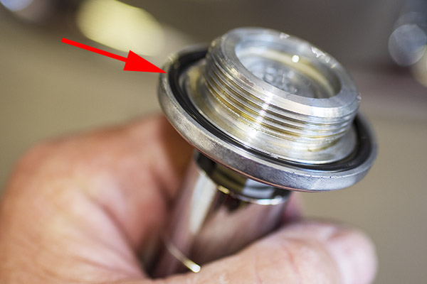
Here’s the access port cover on the left side of the engine.

Remove the access port cover on the left side of the engine with the 14mm Allen drive.
Note that the access port cover is sealed with a rubber o-ring. Don’t lose this part.
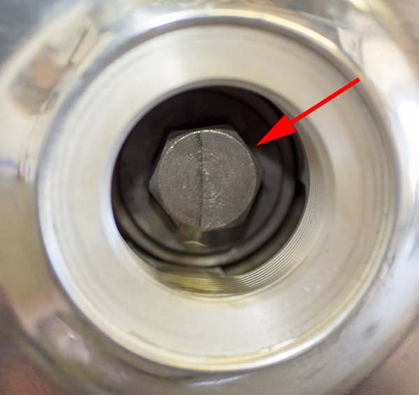
If you peek inside the access port, you’ll see a 17mm bolt head. This is where the 17mm socket is used. You can crank the engine by hand (always going counterclockwise, never clockwise) to bring the crank to a position where the valve being adjusted is not being lifted by the cam lobe. This is known as getting the lifter on the cam’s base circle, and that’s what we want when we make the adjustment.
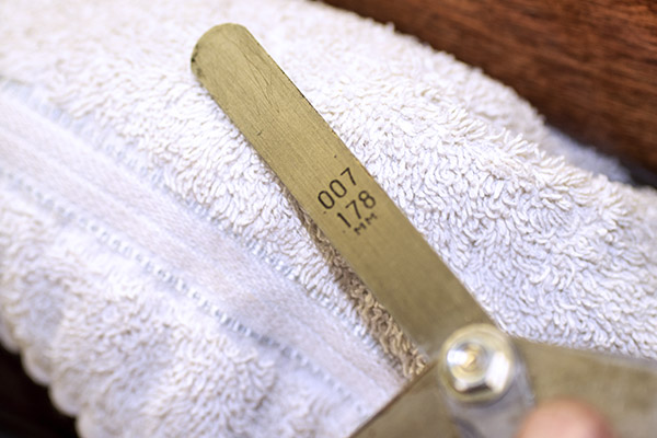
I had a feeler gage from way back tucked away in my tool cabinet. If you don’t have one of these tools, they are available on Amazon. We’ll need the 0.003 inch (or 0.076mm) feeler gage for the intake valve adjustment, and the 0.007 inch (or 0.178mm) feeler gage for the exhaust valve adjustment. The intake valves are the ones on the rear of the engine (closest to the fuel injectors) and the exhaust valves are the ones on the front of the engine (closest to the exhaust headers). I know. Duh.

This valve adjusting business is done by feel with the use of the feeler gage. I guess that’s why they call it a feeler gage. You want to make the adjustment such that after you make it, there’s a slight drag on the gage as you move it back and forth between the valve stem and its actuator (you get the “feel” of this slight drag; hence the “feeler gage” name).
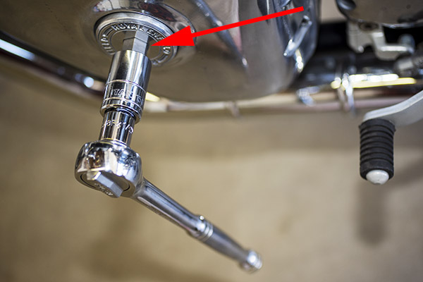
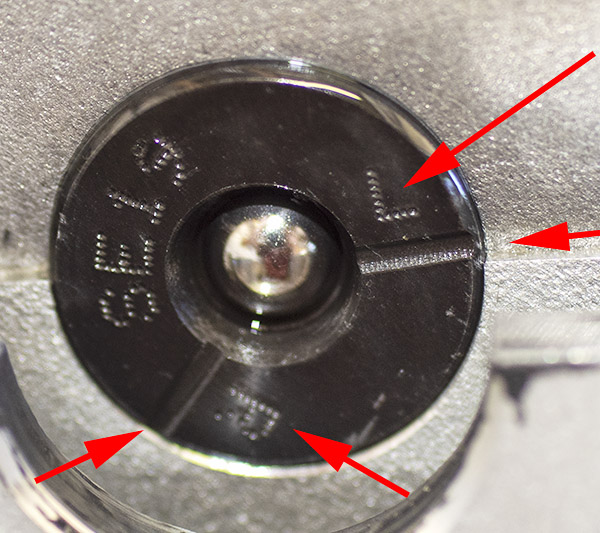
Enfield makes it easy to get the engine rotated to the right spot so that the lifter is on the cam’s base circle with a handy indicator located in the cylinder head. It’s on the engine’s left side as shown in the photo below. The indicator is marked with an L above a scribe line, and an R above a scribe line.
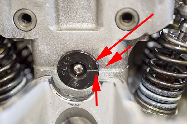
Turn the engine by hand with the 17mm socket (again, always counterclockwise, never clockwise) until the L and its scribe line are aligned with the line on the casting as shown below. We want the L and its scribe line aligned with the corresponding line in the casting when we adjust the valves on the left side of the engine. After we’ve adjusted the valves on the left side, we’ll want to do the same thing to get the R and its scribe line aligned with the line in the casting to adjust the valves on the right side of the engine.
When the crank is appropriately positioned (for the left side of the engine, as shown above), we are now ready to adjust the valves.

The actual valve adjustment is accomplished by loosening the bronze-colored valve stem lock nut with a 10mm wrench, then making the adjustment with a flat bladed screwdriver in the adjuster screw slot, while positioning the appropriate feeler gage blade between the adjuster and the valve stem. This is what controls the gap between the adjuster and the vavle stem. When the gap is what it’s supposed to be, lock the adjuster in place with the locknut. We do this for both intake valves with the 0.003-inch blade, and both exhaust valves with the .007-inch blade.
After we’ve done the left side of the engine, we similarly rotate the crank to align the R index mark and then we adjust the valves on the right side of the engine. The R has to be on the right side of the index plate so it reads right side up.
At this point, I rotate the engine two complete turns by hand and use the feeler gage to check the valve gap again. If it’s not good I redo the above adjustments. This is just a check. For me, it’s always been good.
So, about that valve cover and the complicated seal between it and the cylinder head. Here’s what it looks like from underneath.

Note that the seal is orientation sensitive. It’s got a little half moon in the seal on the left side. As mentioned above, getting the valve cover off was a challenge. Getting it back in place with the seal properly positioned was even more of a challenge. But neither steps were really that bad. The good news is that this was the toughest part of the job, and it wasn’t that tough.
After you finish adjusting the valves, assembly is the reverse of disassembly. There are three cautionary notes:
-
-
- Use a shop rag or two on the motorcycle frame so you don’t scratch the frame or the fuel tank when you reinstall the fuel tank.
- When you remake the fuel line quick disconnect, make sure you feel it click into position. It’s possible to not fully make the connection, which could result in pressurized fuel being pumped out over your hot engine. That would not be a good thing.
- When you reinstall the valve cover, make sure the seal between it and the cylinder head is correctly positioned. If it is not, oil will leak from this interface.
-
So there you have it. For me, that’s $581 (what the closest Enfield dealer charges for a valve adjustment) going in the Baja kitty. Or maybe the reloading components fund. Whatever. It’s not going into the dealer’s pocket, and that’s the point.
Enfield did a nice job engineering these bikes, I think, and they made the valve adjustment process straightforward. It would have really been cool if the valve cover was designed so that it could be removed without taking the body panel, seat, and fuel tank off (like on an old airhead BMW or a Moto Guzzi), but hey, it is what it is, and what it is is way less complicated than most other modern motorcycles. There’s also an argument to be made for hydraulic valves (which never require adjustment), but hydraulic lifters weigh a little more and don’t work well at high rpm.
More on Enfields? Hey, read our series on taking two Enfields (a 650 and a Bullet) through Baja. It’s what prompted me to buy my Enfield!
This idea on online maintenance tutorials was something we started at CSC Motorcycles with the RX3 250cc adventure touring platform introduction. The market received it well and we had a lot of fun assembling the tutorials. CSC was well ahead of the curve on this sort of thing and it is one of the many reasons their bikes have done so well.