
You know, you can have a lot of fun dreaming up titles for blogs. When I told good buddy Mike about this one, he’s the guy who suggested the above. Yeah, it’s racy, but it’s not what you think. This blog is about timing. Life, success, good comedy, and a host of other things are all about timing.
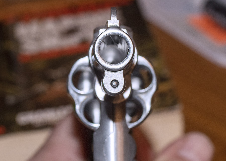
Take revolvers, for instance. Timing is critically important. For a revolver, timing refers to having the chamber precisely aligned with the barrel when the hammer drops. If it’s not, the barrel becomes a salami slicer, which is good if you’re a mohel but bad if you’re a shooter (or another shooter on the firing line).
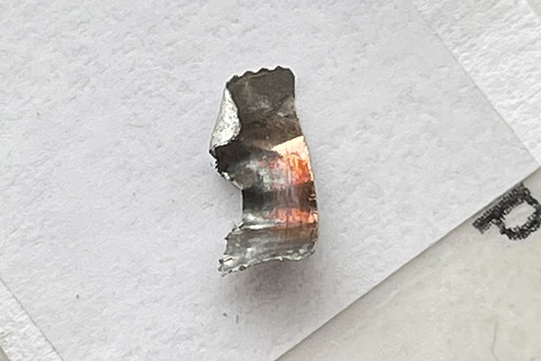
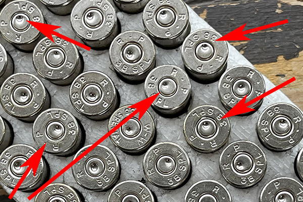
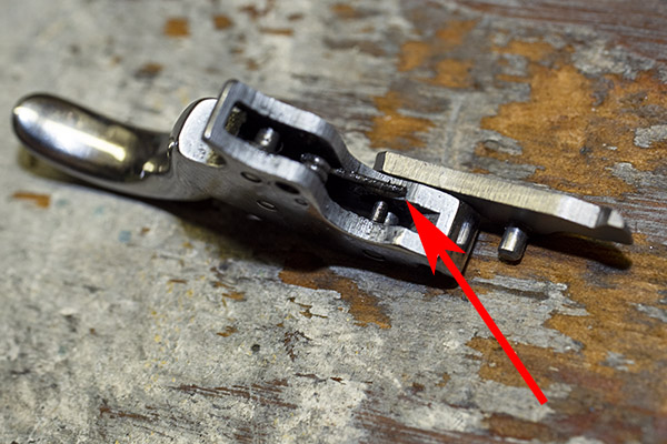
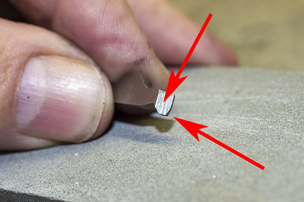
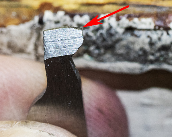
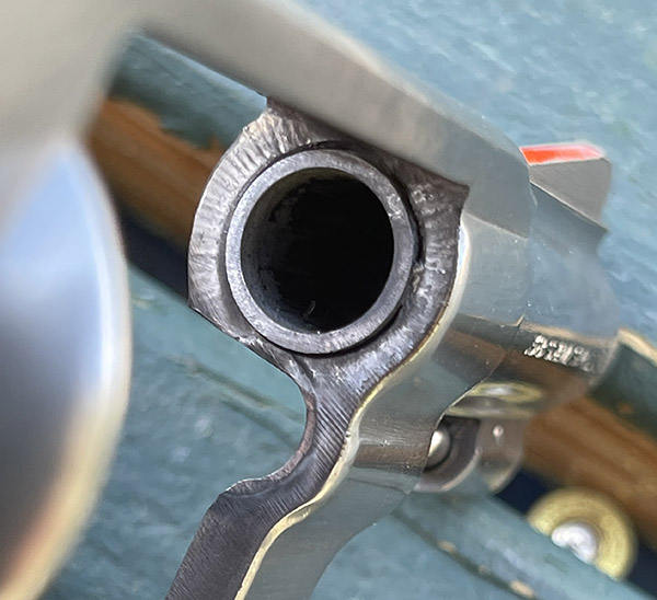
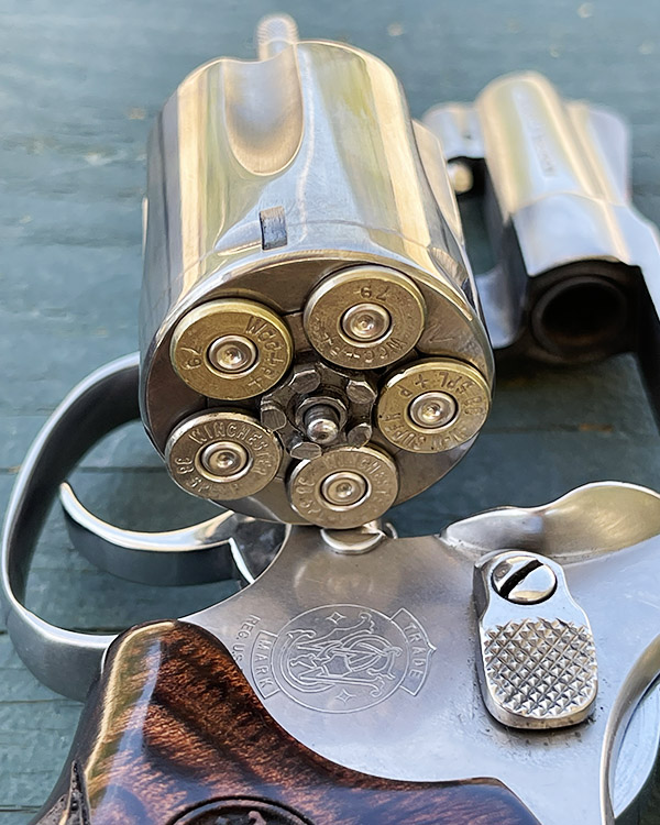
Take a look at that lead shaving in the photo above. It’s what squeaked out of my Model 60 and went sideways at high velocity between the cylinder and the barrel. It did that because the revolver went out of time. Primers can be another indication of incorrect revolver timing, as shown in the photo below. When the firing pin’s primer indentations are offset like you see here it means you’ve got trouble in River City (or anyplace else you’re firing the revolver).
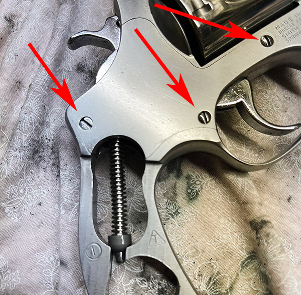
This blog explains how to correct an incorrectly timed revolver. We’ll start, as always, by making damn sure the gun is unloaded. Once we’re satisfied it is unloaded, the next steps are to remove the revolver’s grips and sideplate. The grips detach with a single screw. Three screws secure the sideplate, and each of them is different. The one at the rear of the sideplate is easy to distinguish because it has a flathead to fit under grips. The other two have domed heads, but they are not identical. The screw at the front of the sideplate is dimensioned such that it locks the yoke in position fore and aft, but it allows it to rotate. If you switch the two domed screws when you reassemble the revolver, the cylinder will not swing out of the frame freely.
Once the grips and sideplate screws are out, don’t try to pry the sideplate off the revolver frame. Hold the revolver over your workbench with the sideplate facing down, and give the left side of the grip frame a few sharp whacks with a plastic mallet or a screwdriver handle. The sideplate will drop out, and the transfer bar will drop with it.
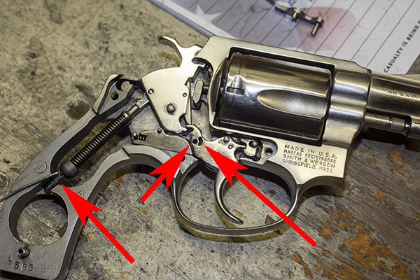
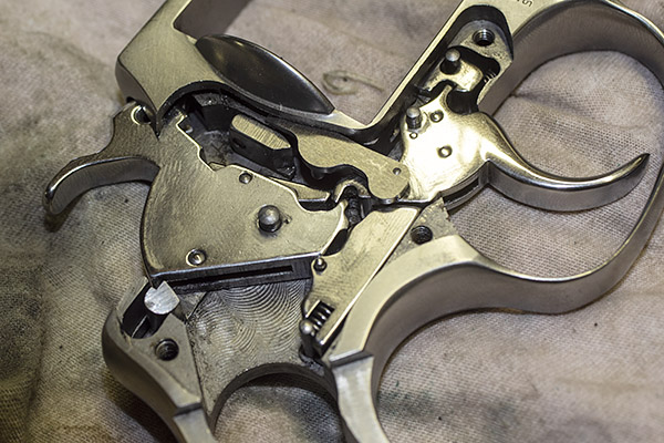
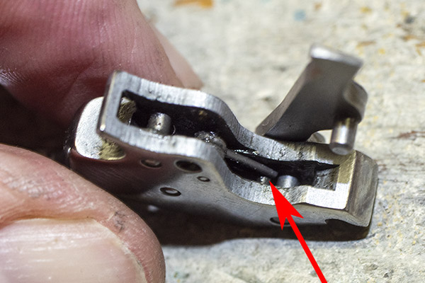
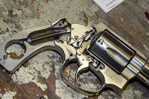
After the grips and the sideplate are off, here’s what the guts of a Model 60 look like. The transfer bar is the piece denoted by the left arrow. It will probably have already fallen off the gun when you removed the sideplate. Our focus in this blog will be on the hand, which is the piece noted by the red arrow on the right in the photo below. The hand will pivot counterclockwise in the photo below. Rotate the hand counterclockwise and you can lift it out.
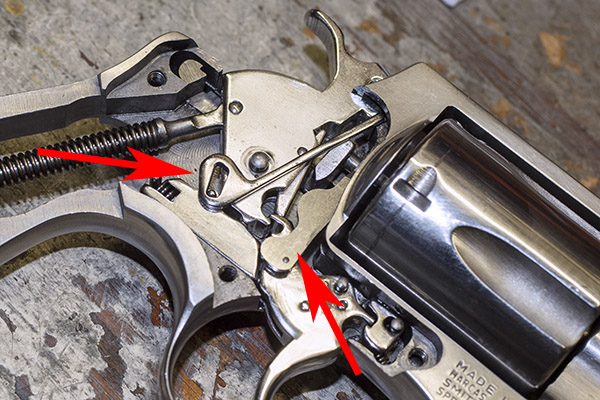
The hand is what moves upward as you pull the trigger or cock the hammer. It fits through a slot in the revolver’s frame to engage the little nubs on the cylinder’s ejector.
Here’s what the hand looks like after you have taken it out of the revolver. The hand on the left (in the photo below) is the one that was in the revolver and Model 60 to go out of time; the one on the right is a brand new one.
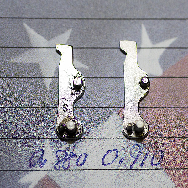 You can see there’s a big difference in length between the old and the new hands. I bought my new hand from MidwayUSA.com. It was about $25.
The next steps involve removing most of the revolver’s internal pieces. You don’t have to do this to get the hand out of the gun, but you will have to remove and reinstall several internal components several times to properly fit the hand. This involves checking both single and double action function testing, disassembling, removing very small amounts of material from the upper part of the hand, reassembling, and repeating the process several times until the revolver is functioning satisfactorily.
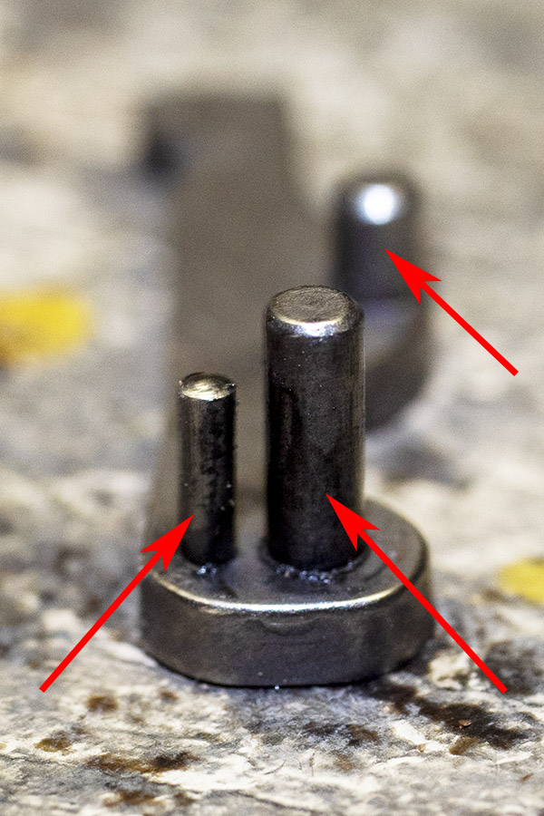
We’re going to remove the hammer spring and yoke using the same paper clip custom tool we used for installing the lighter hammer spring (denoted by the left arrow). Those other two arrows denote where the hand’s two bottom pins fit into the trigger. We’ll come back to that later.
This next two photos show the hand’s bottom pins. The third pin is a stop. We’ll come back to that later, too.
At this point, push the revolver’s cylinder release forward, lower the cylinder out of the frame, and slide the yoke and the cylinder off the revolver.
We’ll next remove the revolver’s hammer. It lifts out to the right. Then we get to the trigger spring and rebound slide. It’s tricky. It’s the piece just below the hammer in the photo below. Note that it has a spring acting against a post at the rear. After you have removed the hand and the hammer, you can pry the rebound slide away from the revolver’s frame, but make sure you cover that spring. If you don’t, it will go flying. Don’t ask me how I know.
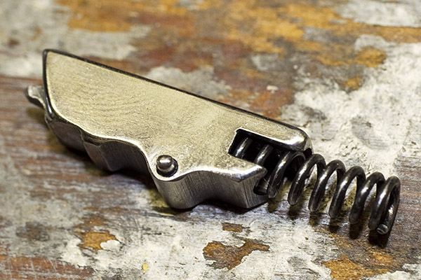
Here’s the trigger spring and rebound slide after removal from the revolver.
At this point, you can lift the trigger out of the revolver.
This is where things get even more tricky. We’ll fit the new hand to the revolver. Doing so will require installing it as delivered to get a rough feel for how much material we need to remove from the hand, reassembling the revolver to check functionality, disassembling again to remove the hand, stoning the upper surface down a little, reassembling, and repeating the process. It took me three assembly/disassembly/reassembly cycles to get it where it needed to be. Slow and gentle is the approach here. You can take material off the hand; you can’t put it back on. Take too much off, and you’ll ruin the new hand.
The first thing we need to do during the reassembly step is install the new hand in the trigger, and that’s tricky, too. There’s a tiny torsion spring in the trigger, and its purpose is to keep the hand pressed forward against the extractor. You can see the red arrows pointing to the spring in the photo below.
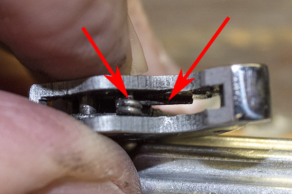
That little spring needs to be on top of the hand’s smaller lower post, and in order to get it there, the easiest way is to push it up from beneath the trigger before you attempt to install the hand, rest the spring on the side of the trigger, install the hand, and then push the spring back into the trigger. Here’s what it looks like with the spring pushed on the side of the trigger.
After you have inserted the hand into the trigger (as you see above), you can then push the spring back into the trigger’s slot.
We are now ready to start the fitting process. Put everything back together again except the transfer bar, the sideplate, and the grips. When you reinstall the rebound bar, make sure the little shaft that extends from the rear of the trigger engages the cavity in the front of the rebound bar. You can see that cavity in the photo below.
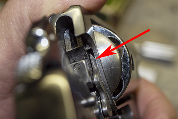
When you look at the revolver from the rear, you’ll see the hand inside the revolver frame slot, and how it moves up and down when the hammer is cocked (if you are firing single action) or when the trigger is pulled all the way to the rear (if you are firing double action). The hand acts against the little nubs on the extractor to rotate the cylinder. You can see one of the extractor nubs in the photo below.
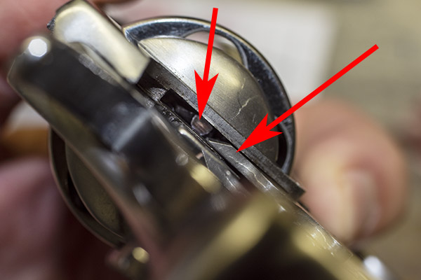
On a new hand, the hand will most likely be too long. The revolver may or may not rotate the cylinder when you actuate the trigger in a double action mode, and the hand probably will not actuate the cylinder when you cock the hammer as if you were firing in the single action mode. That is because the hand is so long it slides along the rear of the extractor nubs without dropping in between them, which it needs to do to ratchet the cylinder so the next round comes into battery. In the photo above, you can see a little bright witness mark at the bottom of the upper red arrowhead where this occurred.
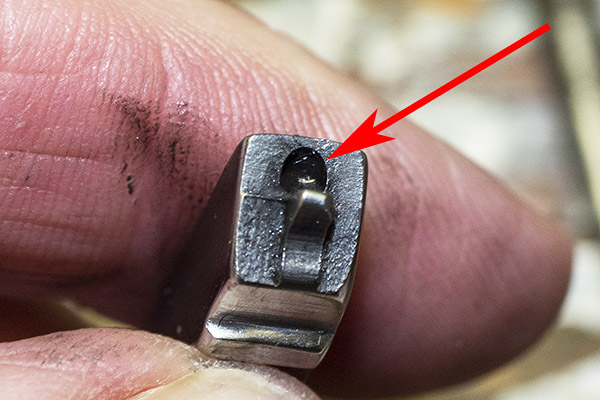
We next disassemble the revolver’s guts as described above to fit the hand to the revolver. We’ll remove a bit of hand material from its top portion using a stone. I angled the top edge of the hand. Here’s what that looks like.
The lower arrow in the photo immediately above shows where I removed hand material. The upper arrow shows the hand’s angled surface that completes the cylinder’s advance. Leave this area alone.
The photo above presents another look at the same angled portion of the hand as it is delivered. The red arrow points to the area where I removed material to fit the hand to the revolver. The larger angled area is how the hand came from the factory. It looks rough as hell, like it is begging to be polished, but I left that part alone and my revolver is silky smooth.
After we’ve done the above assemble/check/disassemble/remove hand material a few times, you’ll get to where the revolver looks the cylinder in place right where it is supposed to be (you’ll need to reinstall the cylinder and yoke to do this). What we want to do is put your finger on the cylinder so that it has a little drag while cocking the hammer. When the hammer is fully to the rear, the bolt at the bottom of the cylinder should click into place. Then we want to do the same thing (put your finger on the cylinder to impart a little drag) and pull the trigger to the rear double action style. The bolt should snick into the cylinder just before the hammer falls.
When you think you’re there based on the above checks, it’s time to fully reassemble the revolver. Lay the revolver on its left side and place the transfer bar on top of the hammer as you see in the photo below. You have to have the transfer bar all the way up so the pin in engages is at the bottom of the transfer bar slot. If you don’t have it positioned as you see below, the sideplate will not fit back on the revolver.
After doing the above, good buddy Paul suggests loading dummy rounds in your Model 60 to make sure it cycles correctly. Before you go to the range after doing this kind of work, it’s a good idea to take some fired cases and cycle them through the gun in both single action and double action modes. If you have some with the primer indentations off center (as shown in the photo at the start of this blog), check to make sure that the new indentations are now more centered (they were on my Model 60). DO NOT put live primers in an otherwise empty case for this test; they can back out of the cartridge case and lock the gun. You also want to make sure that there’s no interference between the new hand and the case rims. I haven’t encountered this on a Smith and Wesson revolver; Paul has on a Taurus revolver.
I used the fired empty cases you see in the photo near the top of this blog (the ones with the off-center primer strikes) and cycled five through single action, and another five through double action. The gun cycled flawlessly, and the previously fired cases now had primer indentations in the center of the primers. Things were looking good, but the real test would be on the range.
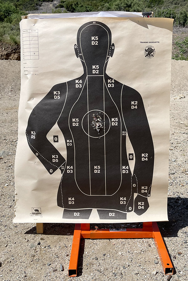
I set up a police qualification target at 7 yards and pumped a box of ammo (5o rounds) through the Model 60 shooting double action rapid fire. Wow, was I pleased with the on-target results.
After the first few cylinders of ammo, I looked at the forcing cone around the frame. Unlike earlier, when there was a heavy lead spatter pattern on the right side of the frame only, the spatter was now evenly distributed around the forcing cone. That’s another indication that the cylinder was centered in the forcing cone (i.e., aligned with the barrel). Things were looking good.
I then examined the primer indentations in fired cases. They were smack dab in the center of the primer, right where they should be.
And folks, that’s it. This revolver is between 50 and 60 years old, and it’s now as good as new. It’s a favored handgun and it does good work, as that target above attests.
Watch the blog, as the Model 60 will continue to appear here. It’s just too good and too much fun to relegate to the safe.
More Tales of the Gun!
Never miss an ExNotes blog…sign up here for free!
Excellent Article
I added your Revolver Hand Timing Tip (as Blog Tip #2) to my site as a Valuable Resource for my customers…
Keep the Great Gun Articles Coming!
Thanks much, Lance. And you can count on continuing Tales of the Gun. Ours is an interesting hobby.
Great job on your Model 60 and a very informative write-up.
Thanks for sharing the procedure
Joe
I probably did too much research on the origin of the simplest machine ever made, which is the lowly screw. Long story short… Screws were invented because of the need of fasteners that would stay secure on firearms. Nails just kept backing out. The first screws were all handmade. Before screws were invented other means of fastening were used such as bent tabs which were used in clocks (and cheap Japanese toys from the sixties) or by “deadening”, the practice of bending over nails with a hammer. Once bent the nail was considered “dead”. Double thick doors were nailed together but it wouldn’t do to have the pointy ends sticking through so they had to be deadened. Hence the term “dead as a door nail”. My same research also revealed that not one single person is attributed with the invention of the flat head screwdriver, it simply came along to install screws. DISCLAIMER- Ok, my research involved reading a single book by a single author and backing it up with internet searches but I truly believe I got to the bottom of it and am now the foremost expert on the topic within the circles I travel in. Time wasted?, I think not.
I often wondered where “dead as a door nail” originated. Muchas gracias.
That was one of my great takeaways from the book as well (providing it is fact but who cares?, the story fits). You can see the heads of deadened nails on large castle and cathedral doors, usually fancy diamond headed things. The next time I see a real one I’m going to look on the other side.
Marcus really got screwed. Nice history I did not know as a machinist. Or the “dead as a door nail” origin. Thanks Marcus.
I’ve always wonder about how revolvers were timed Joe. Very informative article.
So the bolt thingy that springs up into bottom of cylinder notch is what actually positions and stops the cylinder in the proper position ?And the hand moves the cylinder into correct position but relies on bolt to locate cylinder correctly if I understand you right?
Does the bolt thingy that comes up under cylinder get wore out also? Allowing cylinder to rotate alittle back and forth?
Always wondered about the timing of everything in revolvers and had some with loose cylinders that rotated back and forth a smidgen with hammer pulled back.
As a machinist I’ve also thought of a go/ no go rod that was .001 under the barrel bore so it would slide into barrel easily and have each end turned down different minute amounts. So as you cocked hammer all the way back, you could then slip the rod thru barrel and into cylinder to see if cylinder rotated exactly into line with barrel.
Maybe way over kill and the forcing cone takes care of any misalignment ????
I talk to much.
Good inputs, Rob. Thanks for commenting.
Joe, you never mentioned semi-automatic revolvers.
Yes, you are right, I did not. There actually is such a thing, as this video shows.
needs more racy photos!