I liked good buddy Jose’s blog about his Marlin Glenfield .22 rifle, and we thought it would be a good idea to include a Rimfire Series category here on ExNotes. When the idea first surfaced, I thought we might have done a blog or two on .22 rimfire firearms. When I searched through our blogs, I found that we’ve already posted six .22 blogs. For your quick reference, here they are:
We’ll be including a category for these on our Tales of the Gun page, too.
Please click on the popup ads!
Watch for upcoming rimfire stories in this series, including a blog or two on the GSG .22 1911, the Ruger Single Six, the Smith and Wesson Model 41, a Mannlicher CZ Model 455, a Trainer CZ Model 452 , a Winchester Model, a Remington Custom Shop Model 504, a Ruger Mannlicher 10/22, a 200th year Ruger 10/22, a target grade Ruger Mark III, a vintage Winchester Model 62, and more. Yep, we like our rimfires. Big time. Stay tuned, Amigos!
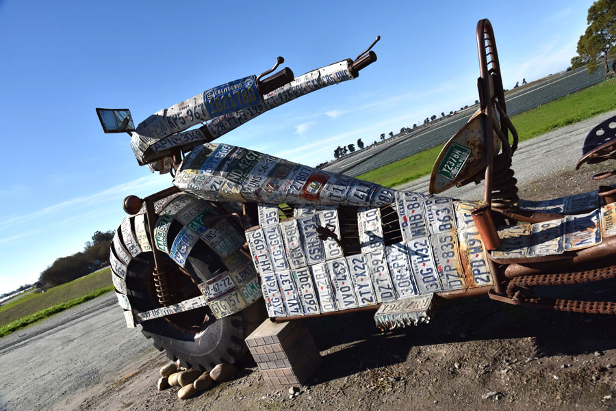
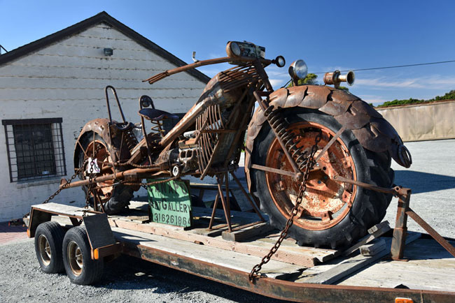
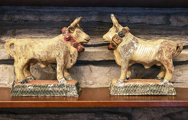
If you’re on the Pacific Coast Highway and you’re riding through the little fishing village of Moss Landing, it’s nearly impossible to miss the moto art at the J&S Eagle Iron and Leather Shop, although that’s exactly what I did on a trek north a few years (no doubt because it was raining so hard). On the way back, though, the sun was out and I when I saw these I knew I had to stop for a few photos. I shot these photos about 5 years ago and I don’t know if these moto sculptures are still there. It might be worth a ride to check it out.
Ernie Buck, the store manager, told me these gigantic bike sculptures are Hecho en Mexico and go for about $20K each. I guess that’s not that far-fetched considering what a new Harley or BMW costs these days, and these things are easily three times the size of those bikes.
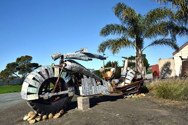
The first moto gigante was constructed mostly of license plates. Bear in mind that all three of these sculptures use giant tractor tires (that will give you a sense of their size). Like I said above, they’re huge!
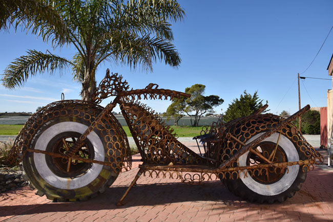
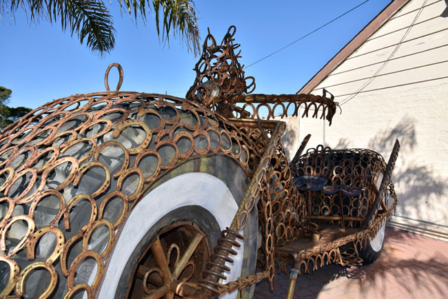
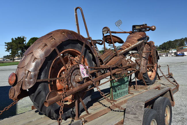
The next one was fabricated from horseshoes. Horseshoes! Imagine that! Where do artists get their ideas?
It was cool. I liked the gangster whitewalls. I had a set of those on my ’92 Softail. You know, the top of those tires was about the same height as me!
The third bike was fabricated almost entirely of shovels.
Maybe the bike above is a Shovelhead (you know, the one that came after the Panhead). It was cool.
You know, the bikes above make for interesting displays, but I wondered where I would put such a thing if I owned it. You’d need a huge lawn or a spacious home in which to display this kind of art, and even then, I’m pretty sure Sue would have none of it. They sure were interesting and they made for cool photos.
The Pacific Coast Highway is an amazing road and it’s always been one of my favorite rides.
200+ pages of single-spaced, profusely-illustrated motorcycle content from the two Joes who started ExNotes. The collected works, so to speak. With selections including magazine articles, road tests, opinion pieces, travel stories, ExNotes blog posts, and even a few listicles. American bikes, European bikes, Japanese bikes, Indian bikes, Chinese bikes, vintage bikes, modern bikes, dream bikes, wild conjectures, and more. A Foreword by none other than Jack Lewis, perhaps the brightest and most literate star in the motojourno constellation. It’s about to land. The book is already written. All we need is the title. That’s where you can help. That, and of course, buying the book.
We’ve got a few titles we’re considering:
Dos Joes Dos Moto Joes Two Good Joes The Two Moto Joes Moto Stories from Joe and Joe The Collected Works of Joe and Joe The Collected Works of Two Moto Guys Motorcycle Stuff Motorcycle Musings Please Click on the Popup Ads
We’re not limiting our title selection to the above. If you’ve got a better idea, let’s hear it. Whoever makes the winning suggestion gets a free, signed copy of whatever we decide to call it. After we’re dead, it will be worth a lot of money, and we’re not spring chickens.
Send us your thoughts in the comments section. Let us know what you think. Operators are standing by.
Good buddy Jose, who has written for us before (I’ll give you a link to his other articles at the end of this blog), sent this story to us a day or two ago. I enjoyed reading it and I think you will, too.
By Jose Armenta
Hi Joe!
I have one you might like….
“Minute of Golf Ball”
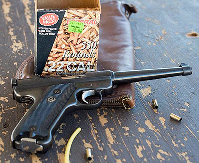
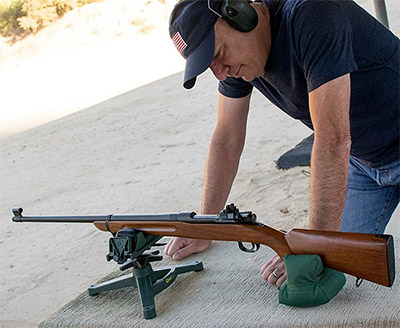
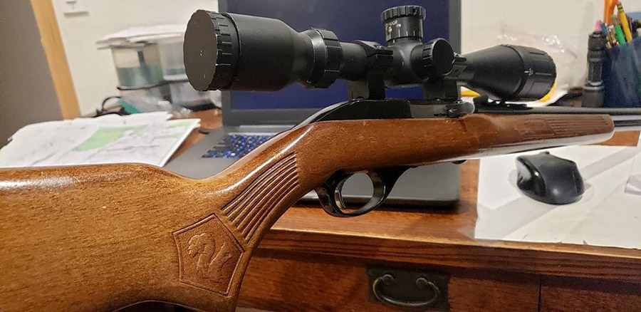
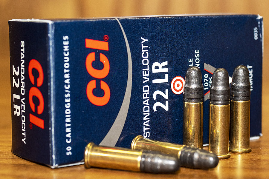
I was at the range two weeks ago on a very busy day fooling around with the first 22 semi auto rifle my parents bought me for Christmas when I was 12 years old (um, I mean Santa Claus did). It’s a Marlin Glenfield Model 60 and it came with a 4x scope.
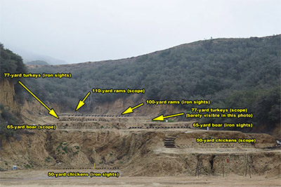
Anyhow some years ago I mounted an inexpensive BSA “Sweet 22” 4×9 scope on it, I mean really inexpensive like 60 or 70 beans. I put four golf balls out on the ground by my targets at 100 yards while some kids and the range hands looked on. Using bulk “rot gut” Federal ammo, I picked off all four balls with four shots. Golf balls fly about 10 to 15 feet when hit with a 22, sort of like when you hit them with a chipper iron. Two kids with a Ruger 10/22 tried bouncing them to no avail. So next range break I set them back up and did it all over again, and the results were 4 for 4!
I told the kids my 50+ year old department store rifle was “minute of golf ball.”
Oh, and yes, it does have the famous Glenfield squirrel stock. I learned to hunt with this rifle so it will always be my favorite.
Who still shoots their first 22 rifle?
Jose
Jose, that’s awesome.
To answer your question (Who still shoots their first 22 rifle?): I know I do, good buddy Greg does, and I suspect quite a few of us do. My first .22 was handed down from my Dad, who bought it when he was 8 years old for $8 in New Jersey of all places (a state with what are probably the most stringent gun laws in the country). I like your story a lot, Jose. It’s a good story, it hits on a topic that many of us can relate to, and it suggests a new blog line: The Rimfire Series. Thanks for submitting this to us, and if you have more stories, please send them in!
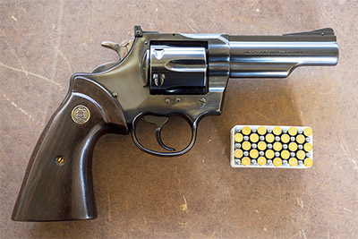
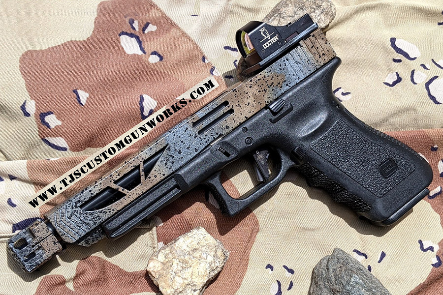
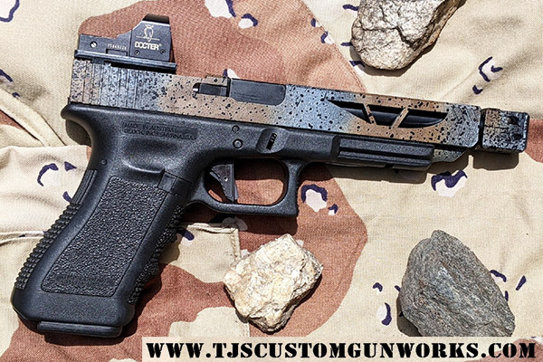
I visited with good buddy TJ of TJ’s Custom Gunworks a few days ago. I’m having TJ work on my Smith and Wesson Shield (we’ll post that story in a future blog). While I was there we talked about the poor trigger pull inherent to striker-fired pistols, and TJ mentioned his custom Glock. He showed it to me and I was blown away. It is beautiful. I’ve seen custom Glocks before, but nothing like the pistol you see here. This one is in a class all by itself.
TJ calls this pistol the Rock Glock for good reason: Check out the granite-speckled, multi-color Dura-Coat finish. The pictures are good, but they don’t do the gun justice. In person, it is visually arresting. Stunning. Beautiful. There are probably more adjectives I could use, but you get the idea.
TJ’s Glock started life as a Glock 22. Here’s a partial list of the custom features TJ incorporated:
Custom Glock 34 9mm slide
Match barrel with MWG compensator
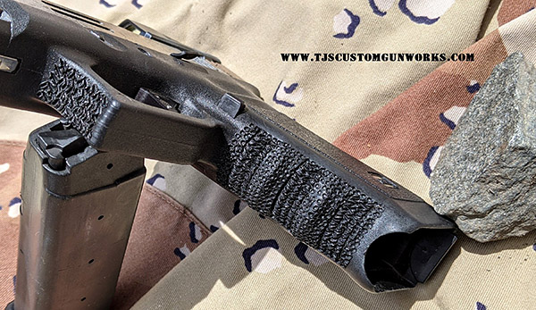
Double-textured grip stippling on the front strap and trigger guard
Custom contoured slide release (it provides a much easier lock and release)
Extended magazine release
Doctor red dot optical sight-scope
Custom Overwatch aluminum trigger
Match connector
Full action and reliability work
Like all of TJ’s custom handguns, this one is not simply a collection of drop in off the shelf custom parts. TJ does a full customize, fit, and polish on everything (the custom parts and the mating Glock components). The Rock Glock is old world craftsmanship applied to modern weaponry. The man is a perfectionist and it shows in everything he does. It’s what keeps me coming back to TJ when I need (or want) custom work done on my handguns.
Please click on the popup ads…it’s what keeps the content coming!
Interestingly, TJ kept the factory Glock striker (the firing pin) in the Rock Glock. He finds them to be much better made than aftermarket strikers. Kudos to Glock on that.
Check out the grip area (both front and back) and the trigger guard. They are deeply stippled to assure a rock-solid, zero slip grip.
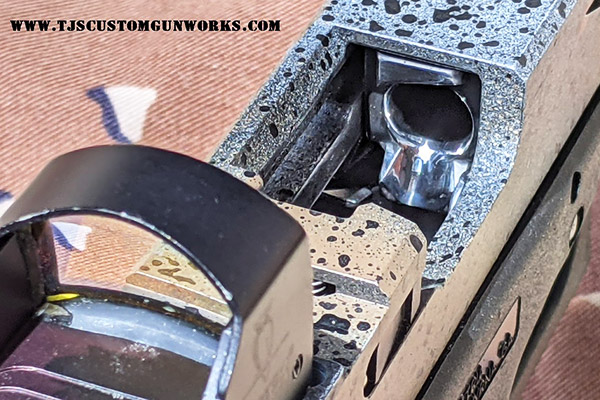
One of TJ’s purposes on any project is to assure absolute reliability. That’s not hype. I’ve experienced it with all the guns TJ’s modified for me. Part of that includes recontouring and polishing the feed ramp on semi-auto handguns. Check out TJ’s touches on the Rock Glock’s feed ramp.
TJ let me dry fire the Rock Glock and I was impressed. He told me that the stock gun had a 6.5-pound trigger pull and it was rough. The Rock Glock now has a 3-pound trigger pull and it is buttery smooth.
It was a good visit and I’m eager to get my Shield after TJ works his magic on it. You’ll get the full report here on ExNotes when I do.
I’ve traveled extensively in Baja and I want to get down there again as soon as possible. It’s the best riding on the planet, the food is amazing, the scenery is incredible, and the people are great. The whale watching is a religious experience. I know Baja is almost indescribably awesome and you do, too, if you’ve been there. When I talk about Baja with folks who haven’t been there, though, the question always emerges: Is it safe?
The short answer is yes. But one time, we came pretty close to it not being safe. On one trip out of many over the last 30+ years in Baja, Susie and I had a bad experience. I almost didn’t write this blog because I didn’t want to scare anyone away from Baja. I’ve been to Baja many times since, and I plan to keep visiting Baja.
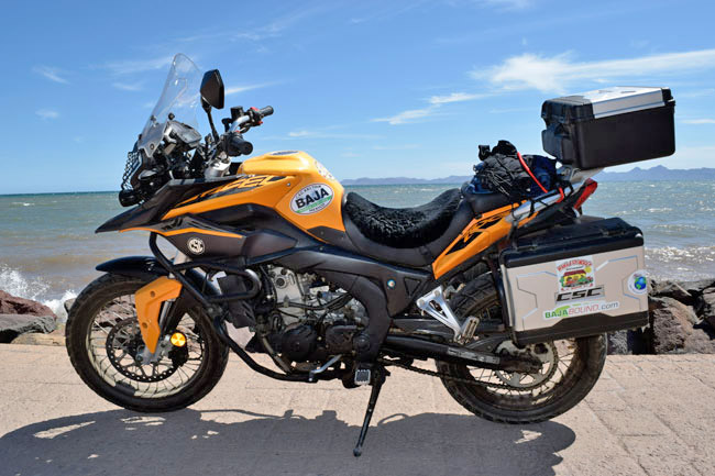
The best bike for Baja…my CSC RX3 on the malecon in Loreto, BCS.
So, with that as an introduction, let me add a bit more. I was setting up the first CSC Baja expedition, with the idea being that we would offer free tours to Baja with the purchase of a CSC motorcycle. That idea worked fabulously well and we successfully ran the CSC tours for years, treating people to the ride of their life, selling a lot of motorcycles, and generally having an inordinate amount of fun. It convinced me that the RX3 motorcycle was possibly the best bike ever for exploring Baja, and I still feel that way. You may disagree, but hey, it’s okay to be wrong.
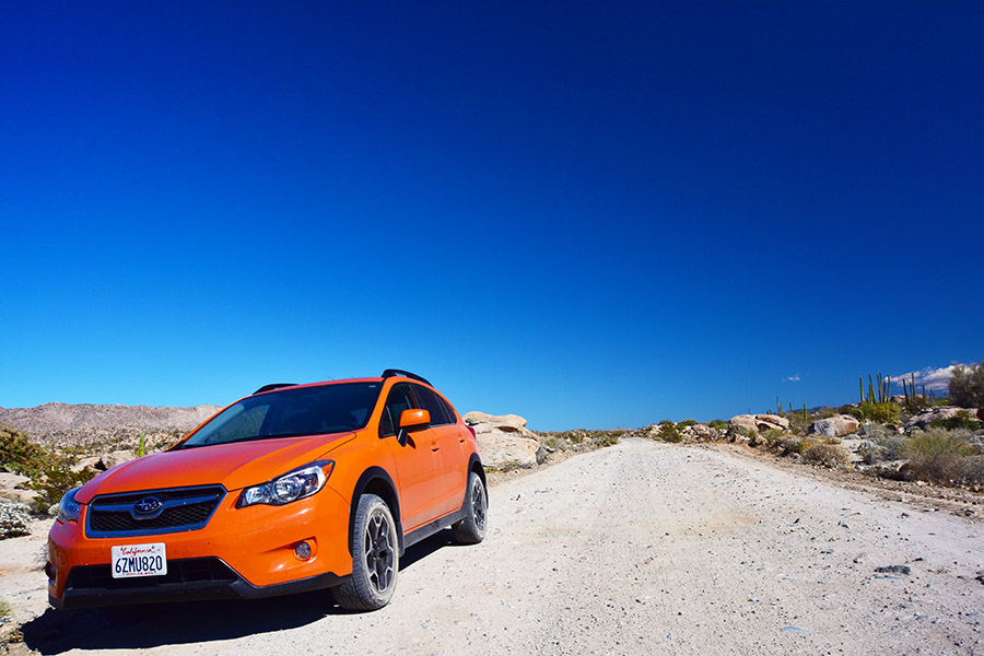
But I digress. To get back on topic, I hadn’t been to Baja in a while and I was taking a big group down, so Susie and I rolled south in my Subie on a pre-ride scouting expedition. With the intro stuff done, here’s the blog I wrote for CSC on that trip.
Susie and I are down in Baja scouting the locations for the Inaugural Baja run, and it sure has been an interesting two days. I didn’t have any Internet access in Catavina yesterday, but I have a spotty connection in Santa Rosalia tonight, right on the Sea of Cortez, and we’ll see how much of this gets through.
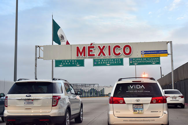
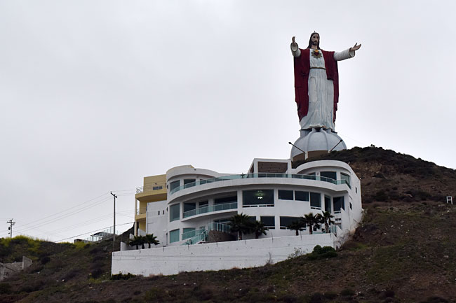
First, a few quick photos of our first couple of stops…
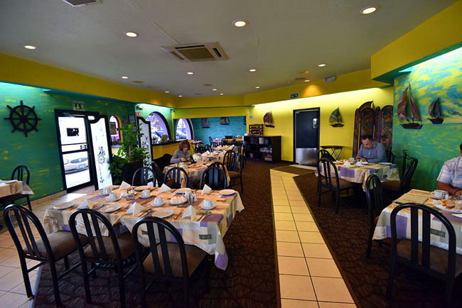
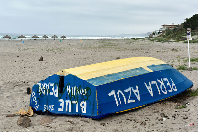
Rolling across the US border into Mexico…Jesus, a giant statue on the way to Ensenada.Breakfast in Velero’s in Ensenada…worth the trip into Mexico all by itself!The Blue Pearl, on the beach…
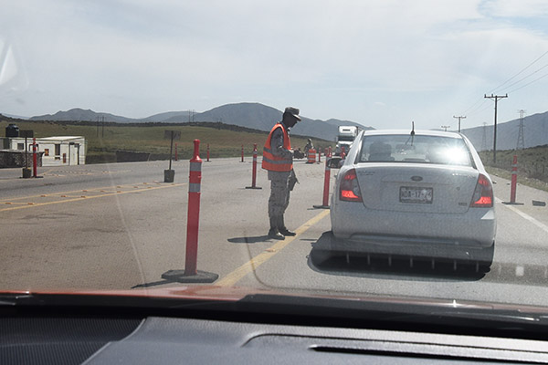
After we rolled through Ensenada, it was on through the mountains south and Baja’s agricultural district. Boy oh boy, did we have an adventure. All that stuff I’ve been telling you about how safe it is down here? Well, I still believe it, but my confidence (and Susie’s) was sorely tested yesterday. See that guy in the photo below? FYI, you’re not supposed to take photos at these roadblocks, and I want you to keep that in mind on our CSC Baja trip…but I never have done too well following rules. I’m talking about the infantryman talking to the car in front of us at our first military roadblock (one of many Puesto Militars) on the way down. He’s the dude standing to the left of the white car.
Mr. “Okay, go ahead…”
Well, things got very interesting after that. That photo was about 175 miles south of the border, just north of San Quintin, where we got caught in a mini-labor riot. Turns out the migrant workers down here are not happy with their wages on the farms. A lot of them come from mainland Mexico with their families, including their kids, whom they evidently put to work picking whatever crops they pick in the fields north of San Quintin. The Mexican government is clamping down on child labor, so that affects these people and they are plenty angry about it. Real angry, apparently.
One of the military checkpoint guys told us the road was closed (that dude in the photo above) about 80 km ahead but he didn’t speak English and he didn’t tell us why. I thought it was because they were working on the road, which happens frequently in Baja, and when that happens the road is closed for about 20 minutes. Then you can proceed. Happens all the time. Amazingly (based on what we found out a few miles down the road) that young soldier let the car in front of us proceed, and then he let us proceed.
About 30 miles later, we started seeing what we thought were small piles of asphalt on the road with lots of wires (you know, like for fixing potholes, which they have a lot of in Baja, but I couldn’t figure out what the wires were). We saw this for about the next 15 miles. We saw hundreds of people milling around, too; far more than I’ve ever seen in these little farming towns.
It turns out that we what thought were piles of asphalt were actually the remains of burning tires. As in “let’s light a fire and shut the main highway down burning tires.” The ag workers have been having demonstrations (actually, labor riots) in the San Quintin area, and we found out (the hard way) that this had been going on for 2 days.
We went a few more miles and encountered a roadblock (more burning tire remnants and boulders blocking the road) with about 50 men milling about who immediately surrounded us. They wouldn’t let us go forward or turn around. One of them threatened us and the Subaru with a 2×4. They were all over the car. Susie had the presence of mind to lock the doors. These guys were mad at the world, and we were the world at that instant. I didn’t know what to do, so I fell back on what always seemed to work elsewhere in the world: I asked the guy who seemed to be in charge if I could pay the toll to get through. He seemed genuinely surprised at that, he thought about it for maybe 5 seconds (duly observed by his subordinate seditionists), and then he realized this might be a viable alternative income stream (Sue designs and manages automated toll roads in the US; it seems to work for us). Our Mexican revolutionary said, “hokay,” I gave him a ten dollar bill, and he told the insurrectionists “let them pass.” Crisis averted. Whew!
The tire remnants continued for another 5 miles, but there were no more roadblocks. While we were stopped at the impromptu toll plaza, one of the seditionists keyed my car door on Susie’s side with initials, presumably the initials of their labor movement (LPS or something like that). I’ll guess I’ll get my body shop guy to repaint it when I get home. That little Subie is going to end up having more bodywork than Joan Rivers. A couple of months ago I dropped one of the RX3s into it. This week it was the Nuevo Mexican Revolution. I’m keeping the body shop business alive in California. Or maybe not. I might leave those initials there as a war wound. At the very minimum, I am re-christening the Subie. She’s no longer the Starship Subaru (sorry, Carl, that was a good moniker, but its time has come and gone). My car is now known as the War Wagon.
We found out from a busload of people in El Rosario (next town down the before getting into the mountains) that they expect the demonstrations to continue for a couple more days and then it should be over. One guy had his windows shattered, probably by the same guy we saw with the 2×4.
Folks, all the tourists down here (and there are lots of us) were talking about this. No one had ever experienced anything like it before, and most of us have been coming down here for decades. It’s a blip, and I’m guessing it is already over. It sure was exciting, though.
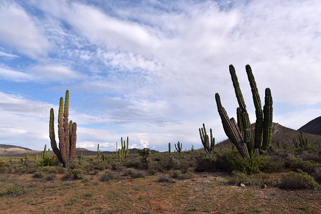
We continued south after that… and that meant it was time for a few more photos.
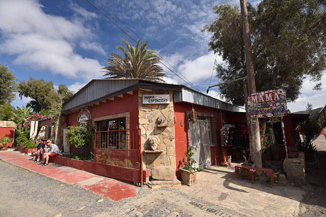
Mama Espinosa’s in El Rosario…great burritos!Cardon cactus in the Vizcaino Desert
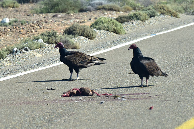
At one point on our way to Guerrero Negro, I spotted several vultures fighting over a dead rabbit. Time to put the 70-300 on the Nikon and see how close I could get.
The Baja Department of Sanitation hard at work.
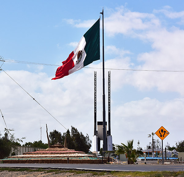
When you roll into Guerrero Negro, there’s a giant Mexican flag flying in front of a giant metal structure (an artist’s interpretation of the Mexican Eagle). You’re not supposed to take pictures here (it’s a military installation), but I still had the 300mm lens on the camera and I got sneaky.
The largest flag I’ve ever seen.
That point is right on the 28th Parallel, which marks the border between Baja and Baja Sur (the two Mexican states in Baja).
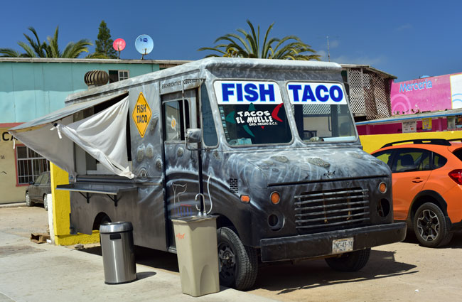
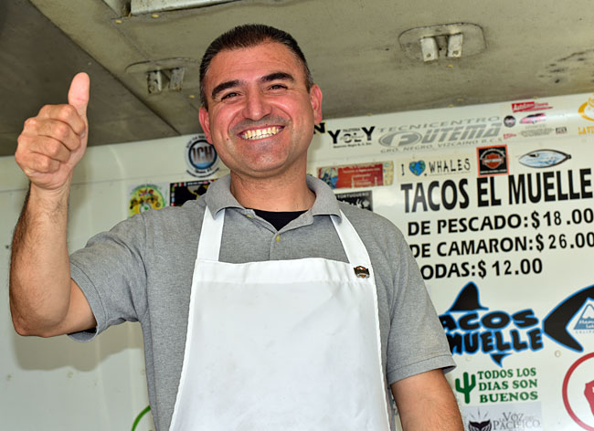
You know, being anywhere near the 28th Parallel and not stopping for a fish taco or two at Tony’s would be a crime. I’ve been stopping at his truck for the last 21 years…every time I come down here. What’s cool about it is Tony always recognizes me, even though sometimes it’s a year or more since I’ve seen him!
The best fish tacos in the world!
My good buddy Tony Lopez, who is a fish taco chef extraordinaire!
Tony told me he’s been in business for 22 years. I bought my first fish taco from him 21 years ago.
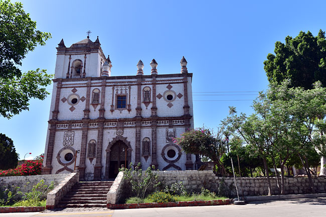
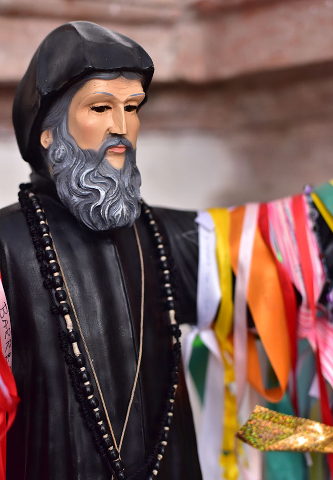
We stopped in San Ignacio next and I grabbed a couple of photos of (and in) the mission there.
The San Ignacio Mission, built by the Jesuits in the 1700s…it’s still in use as a working churchFlowers inside the MissionOne of the figures inside the San Ignacio Mission
That’s it for tonight, my friends. Time to sign off and get some shuteye. We’re headed south again tomorrow. Watch for more photos!
So there you have it. With more than three decades of exploring Mexico under my belt, this was my one negative Baja experience. I communicated the above to all the followers we had on the CSC blog and asked if they wanted to change the trip to someplace else here in the US, and everyone answered with a resounding No! We did the Baja trip with 15 or so riders, and we did several more CSC Baja rides after that. Every one of those trips was a blast. Here’s a video I prepared from the first CSC ride:
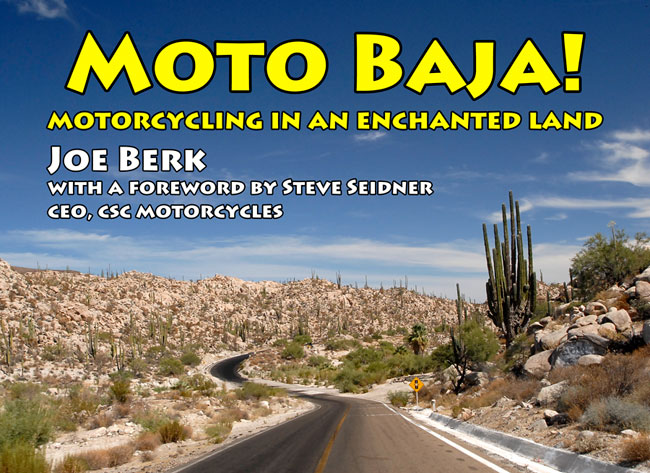
You can read more about Baja and our adventures down there in Moto Baja.
I made a lot of good friends on those Baja rides, many of whom still ride their CSC motorcycles and many of whom regularly follow the ExNotes blog. You’ve seen their comments here over the last four or five years.
To me, Baja is the best riding there is. If you’re headed into Baja, make sure you get insurance. It’s not likely you’ll need it, but the Mexican government requires that you be insured and your regular insurance won’t cover you in Mexico. The insurance provider we always go with is BajaBound.
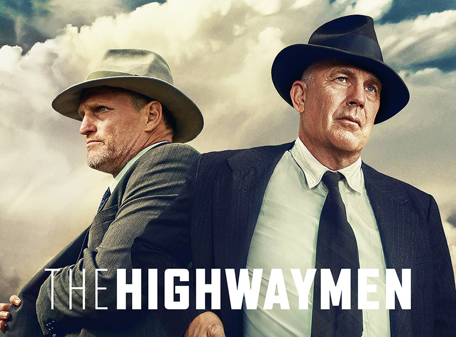
The Highwaymen, starring Kevin Costner and Woody Harrelson, is not a new movie and maybe you’ve seen it already. But if you haven’t, it’s worth watching. In my case, it was worth watching again. I’d seen it twice already when it popped up on the Netflix menu last night, and I watched it a third time. It was great. There have been a few movies and a lot written about Bonnie and Clyde; in my opinion, this movie stands way above the other stories.
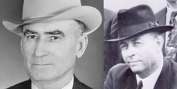
The real Frank Hamer was a hell of a man (as was Maney Gault), although one of the earlier Bonnie and Clyde movies portrayed him as a bumbler and a buffoon. His widow sued Warner Brothers over that and the studio settled out of court. This movie sets that record straight.
Maney Gault (left) and Frank Hamer (right).
The story is about two Texas Rangers (Frank Hamer and Maney Gault) coming out of retirement to track down and kill Bonnie and Clyde. I don’t know how close it adheres to what actually happened, but that doesn’t matter (at least to me). From what I’ve previously known and the research I did online, I think The Highwaymen stays pretty close to the truth. It’s a hell of a story and it’s extremely well done. It hits home for me, too. I’m an old guy and I can sympathize with the two geezers played well by Costner and Harrelson. Their aches and pains made me laugh. I don’t know that I’ve ever seen a bad movie with Harrelson in it; I have seen one or two turkeys with Costner. But in this film both actors were superb (as was the writing) and I appreciated the attention to getting the firearm details right. There’s a gunstore scene that’s awesome. In one of the opening scenes, Hamer is shown to have a pet wild boar. I tried to find out if that was true and what popped up on Google was inconclusive. There are references to his having a pet javelina.
Keep the content coming: Please click on the popup ads!
Trust me on this: The Highwaymen is a wonderful flick. Watch it and you can thank me later.
Two or three years ago Joe Gresh and I provided product reviews on our Viking motorcycle jackets. We like them a lot and you may have noticed that Viking advertises on our website. Both jackets have given us good service and I’ll provide links to those reviews at the end of this blog.
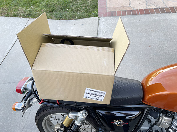
The topic today is the Viking Momentum small street and sportbike tail bag. I’ve found bags like this to be ideal for my travels through Baja and elsewhere. I used similar equipment on my KLR 650 and I found that I could carry more than I needed in Baja and elsewhere. Gresh suggested the Viking bag and I ordered one. It arrived quickly and it was well packaged.
The Viking Momentum bag arrived in a robust cardboard box.
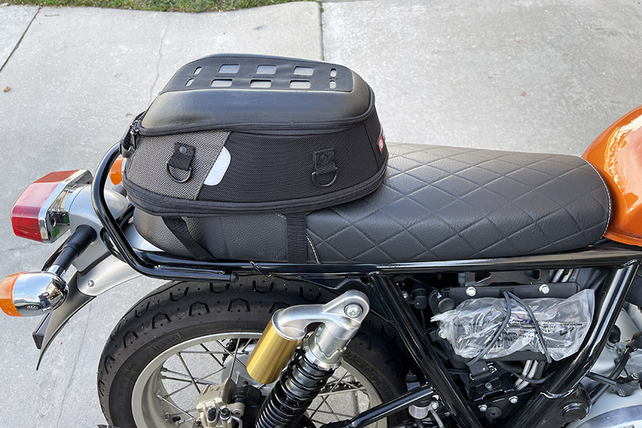
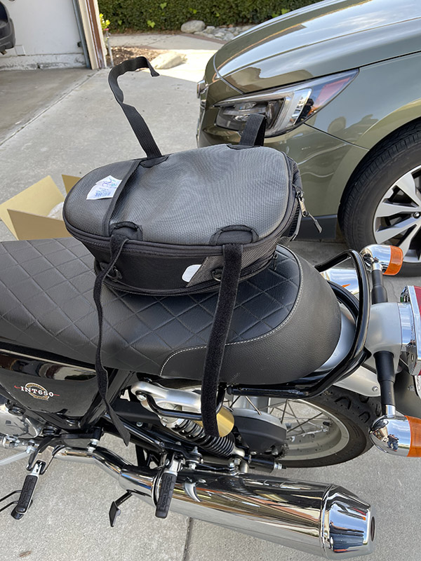
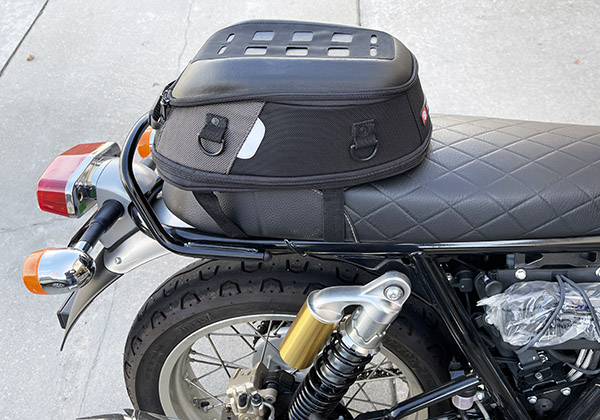
After taking the Viking bag out of the box, I put it on my Royal Enfield. The size was about perfect. What I especially like is that I can swing my left over it when getting on and off the motorcycle. With larger tail bags, getting on and off the motorcycle becomes a problem, but not with the Viking bag.
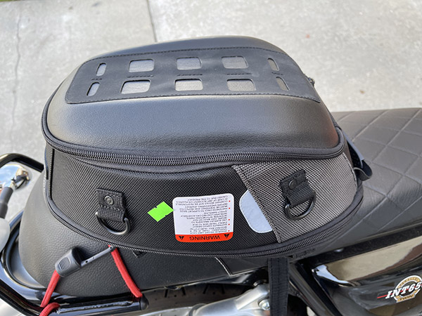
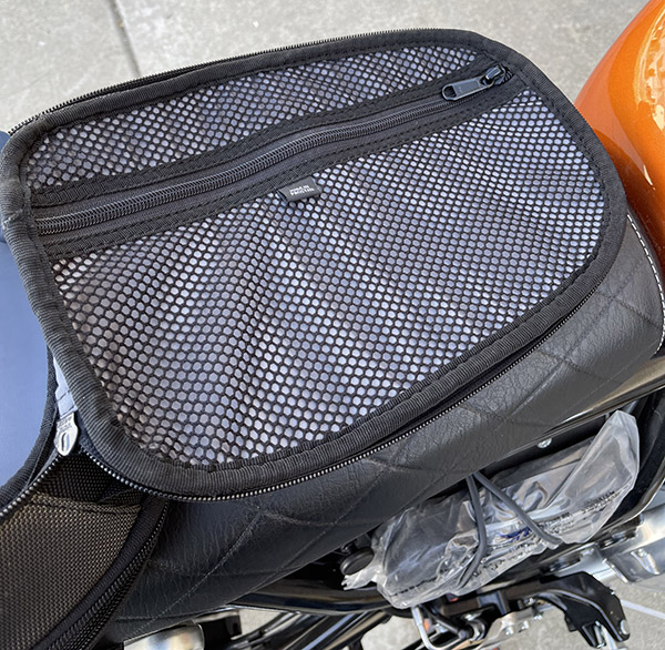
The Viking Momentum tail bag.
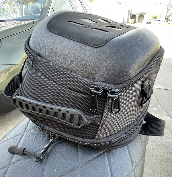
The Viking bag has a hinged lid and lots of mounting points. I’ve not used the slotted deal on top of the lid yet. It looks cool. The bag also has a carrying handle. It’s a well-designed and well-built motorcycle accessory. I examined the bag closely and I am impressed with the build quality. I could not find any defects and no indications of sloppy workmanship.
The Momentum has a carrying handle and two zipper handles for opening an expanding the bag.
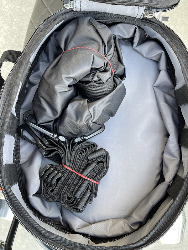
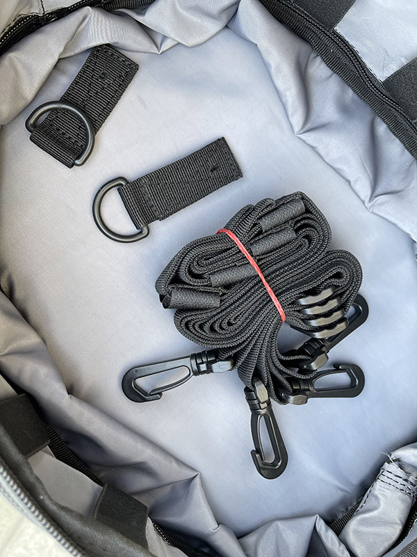
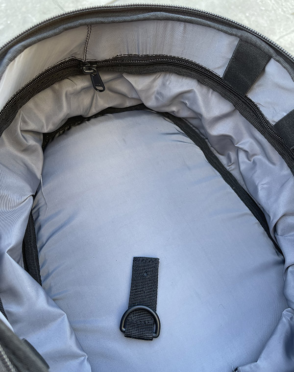
Before I installed the bag on my Royal Enfield, I opened it to see the interior. The Momentum comes with a rain liner, a set of straps, and spare nylon web bungee cord attach points. You can rivet these to the bag (in addition to the four already present) or you can use them as replacements if the ones on the bag detach.
Inside the Momentum I found a rain liner and extra straps. You can use the extra straps for additional tie down points. I think I could use the straps to turn the Momentum bag into a backpack.Extra straps and spare D-ring attachments.
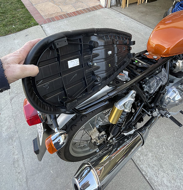
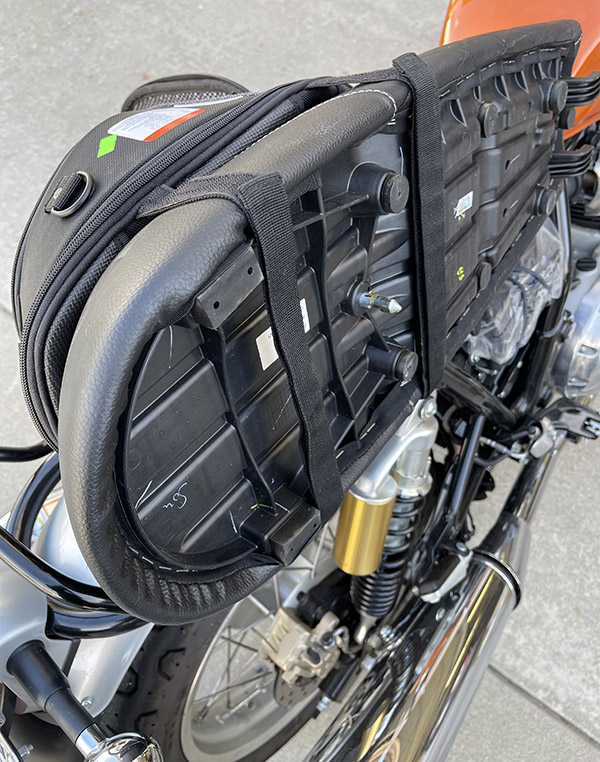
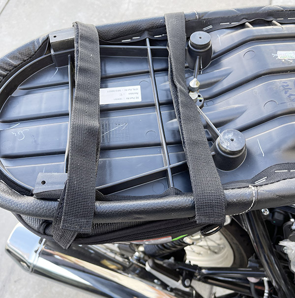
The Viking Momentum bag has four Velcro straps on the bottom. These pass under the seat, stick to each other, and secure the bag to the seat.
The Momentum upside down. The Velcro straps pass under the motorcycle seat and attach to each other.
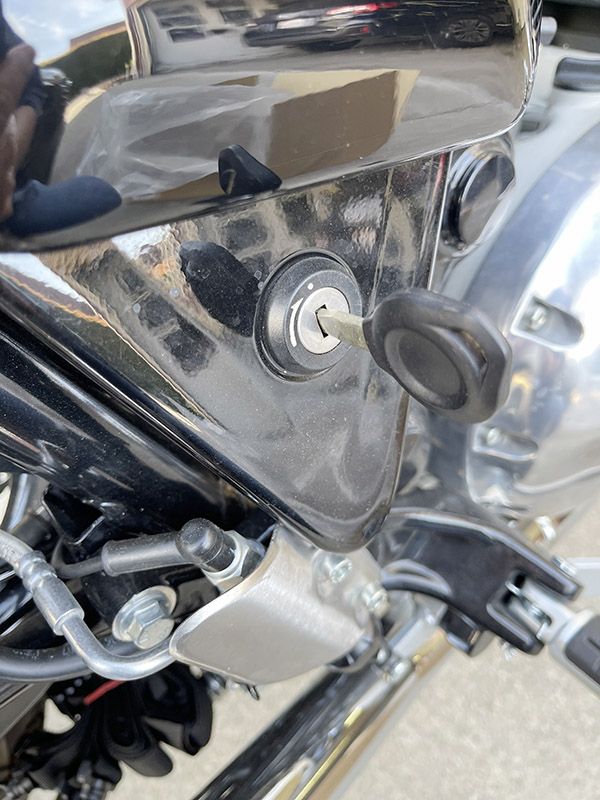
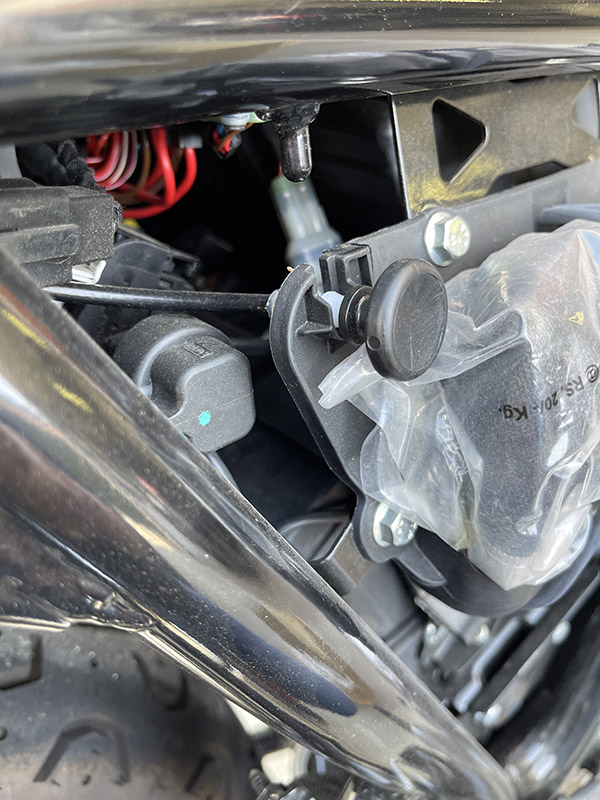
To mount the bag, I took the seat off the Enfield. The Enfield and Viking designs makes this easy. On the Enfield, the ignition key unlocks the right side panel, it comes off, and that reveals a cable pull button that unlocks the seat. Easy peasy.
Unlocking the Enfield side panel to gain access to the seat release.The Enfield’s seat release.The Enfield seat removed from the motorcycle.
Once the seat was off the bike, it was a simple matter to mate the Viking Momentum’s mounting straps underneath.
The Momentum tail bag strapped to the Enfield seat.
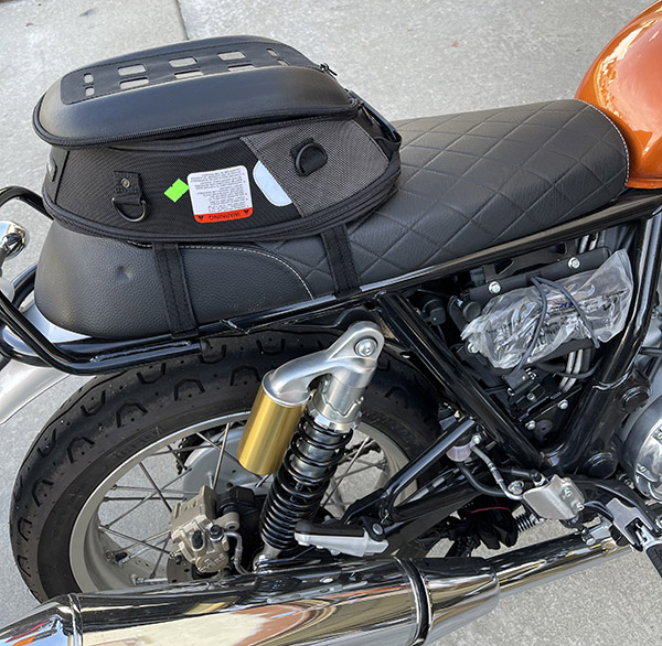
I first mounted the seat so its carrying handle faced forward, as shown below. Then I reversed it. I’ll say more about that in a bit.
The Momentum installed on the Enfield.
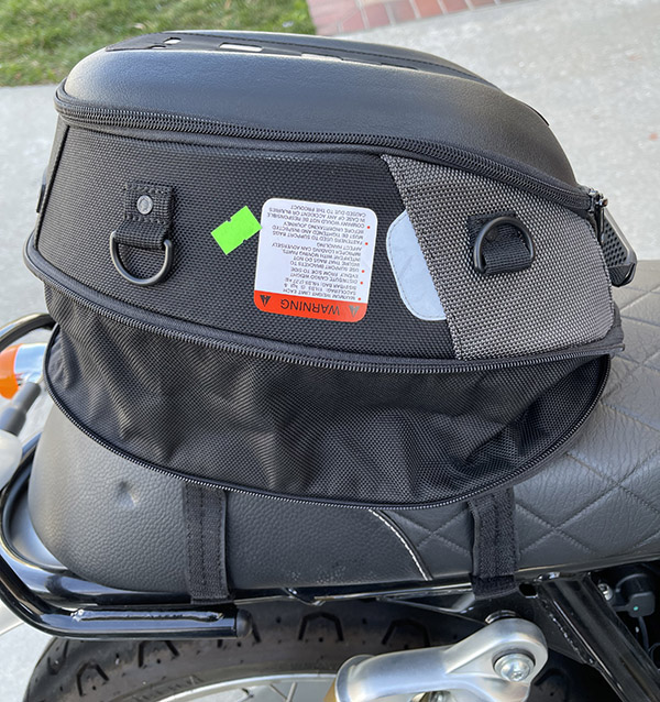
The Viking bag has two zippers around the exterior. The upper one is for the lid; it provides access to the bag’s interior. There’s another zipper around the bag’s base; unzipping it allows the bag to expand and approximately doubles its volume.
With the bottom seat unzipped, allowing the Momentum to expand.
I thought it would be cool if the expanded bag would hold a full-face helmet, but it did not. That’s okay. If I put my helmet inside, there wouldn’t be room for anything else.
There are a couple of zippers inside the Viking bag. One is on the bag’s inner walls. The other is on the underside of the lid. You can store things in the lid compartment like your phone, a map, a Baja tourist visa, your BajaBound insurance paperwork, and other stuff.
The Momentum interior.The underside of the Momentum lid. You can unzip the zipper and store small items inside the lid’s pocket.Like most motorcycle apparel and many luggage items, the Momentum is manufactured in Pakistan.
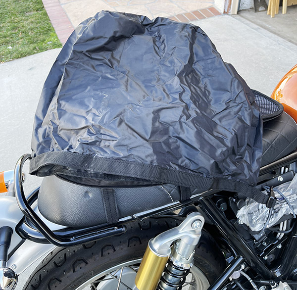
The Viking Momentum includes a rain liner. It packs up compactly. You can keep your stuff dry in the rain liner inside the Momentum bag. It’s a nice touch.
The Momentum rain liner.
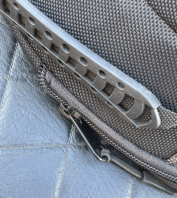
With the Momentum bag’s handle facing forward, I didn’t like how the bag was positioned on the seat. It provided adequate room, but no extra room. The Enfield has a hard seat. I’m getting older and my butt is aging along with the rest of me. I need extra room to move around on a motorcycle seat, and with the bag mounted with the carrying handle forward I didn’t have any extra room. I also noticed that the base zipper (the one you unzip to expand the bag) pull was digging into the Enfield’s Naugahyde surface. I didn’t want to disrespect the Nauga that gave up its hyde for my seat, so I turned the bag around and moved it more toward the rear.
With the Momentum mounted with the handle facing forward, the expansion zipper toggle is against the seat surface. I turned the bag around to eliminate this issue.
When I did that, the Velcro straps are still captured by the seat’s base mounting points (the bag won’t slide off), and I eliminated the zipper-to-Naugahyde interference.
The Velcro straps secured on the motorcycle seat after reversing the bag.
Cosmetically, the seat looks great in either orientation.
The Momentum mounted in the reverse position. The expansion zipper handle is off the seat.
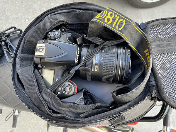
I once led a bunch of guys on a short Baja weekend ride about 15 years ago. One had a Harley, he was new to motorcycling, and he had never done an overnight ride. We met at a Denny’s before heading for Mexico, and when he rolled up on his Electra-Fried, he and that Harley looked like they escaped from the opening scene on the old Beverly Hillbillies show. The only thing missing was Granny in her rocking chair. He told me his saddlebags and his Tour Pak were stuffed, and he also had two or three gym bags bungied to the bike. This was a weekend trip to San Felipe, about 130 south of the border, and we were only staying two nights. My KLR had a medium tank bag and nothing else (and that tank bag also held a camera). “I’m ready for a week down there,” my friend announced from his adventure Glide.
“Well,” I said, “I’ve got my Nikon and a spare set of underwear, so I guess I’m good for a week, too.”
My boat anchor Nikon D810 and a Nikkor 24-120 lens in the Momentum. I really like this. The camera and the lens cost almost as much as the Enfield.
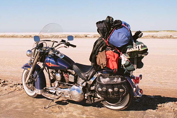
I guess I shouldn’t make fun of that guy. I get it; he was at the front end of the learning curve, and we’ve all been there. I once took an overpacked Harley into Baja, too. We were going to Cabo, taking the ferry to mainland Mexico, heading down to Guadalajara, and coming back through Sinaloa cartel country (you can read about that trip here). I did not yet know about the virtues of traveling light and good ballistic nylon gear like the Viking Momentum bag.
How not to pack a motorcycle. The Momentum tail bag is a much better approach.
The point is this: You don’t need to carry a lot on a motorcycle trip (even if you write a blog), and you can get a lot of stuff in the Viking Momentum. I like it. The Momentum tail bag is a good deal; on the Viking website it retails for $99.99.
So there you go: My take on the Viking Momentum tail bag. It’s a good thing to have for your motorcycle but don’t take my word for it. Listen to what Bernadette has to say.
I mentioned above I would provide links to the Viking motorcycle jacket reviews. Here’s mine, and here’s Joe Gresh’s.
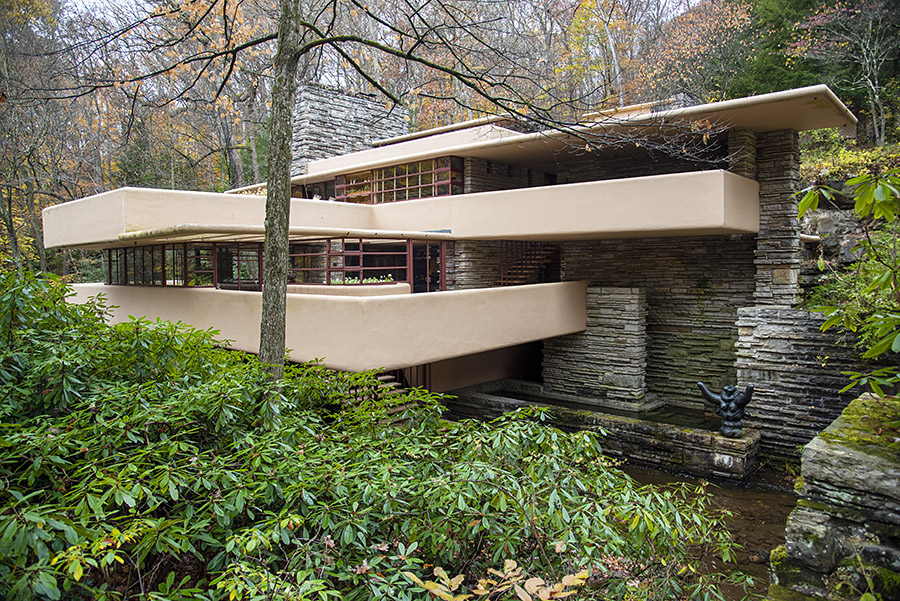
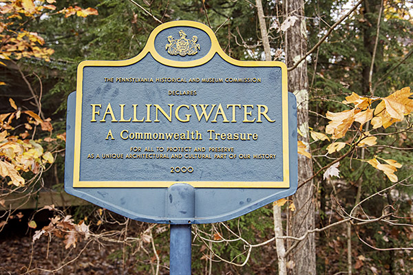
Fallingwater, a famous Frank Lloyd Wright structure in southwestern Pennsylvania, is a place we have long wanted to visit. We finally checked that box late last year and it was well worth the trip. It’s one of Frank Lloyd Wright’s most famous architectural accomplishments, designed in 1935 and completed in 1939 for the wealthy Kaufman family. The Kaufmans owned a large department store empire in nearby Pittsburgh, and Fallingwater was their vacation home. The Kaufman family turned the estate over to the Western Pennsylvania Conservancy and it now operates as an area open to the public.
A Commonwealth Treasure indeed!
The Kaufman family’s request to Wright was straightforward: They wanted something unique, something that merged the mountains’ natural beauty with the architecture, and they wanted the local stream to run through the home. The resulting home became one of Wright’s best known accomplishments. Frank Lloyd Wright had a distinguished career and he is arguably one of the most famous architects who ever lived. Fallingwater is the only Wright home open to the public.
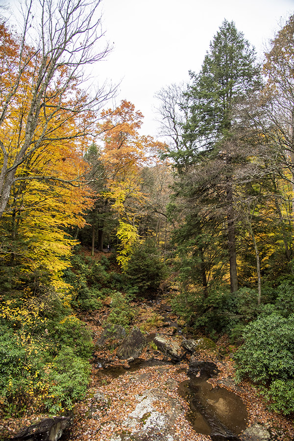
A river runs through it…the view from one of the balconies at Fallingwater. Check out the leaves turning color.Note the layered sandstone construction.
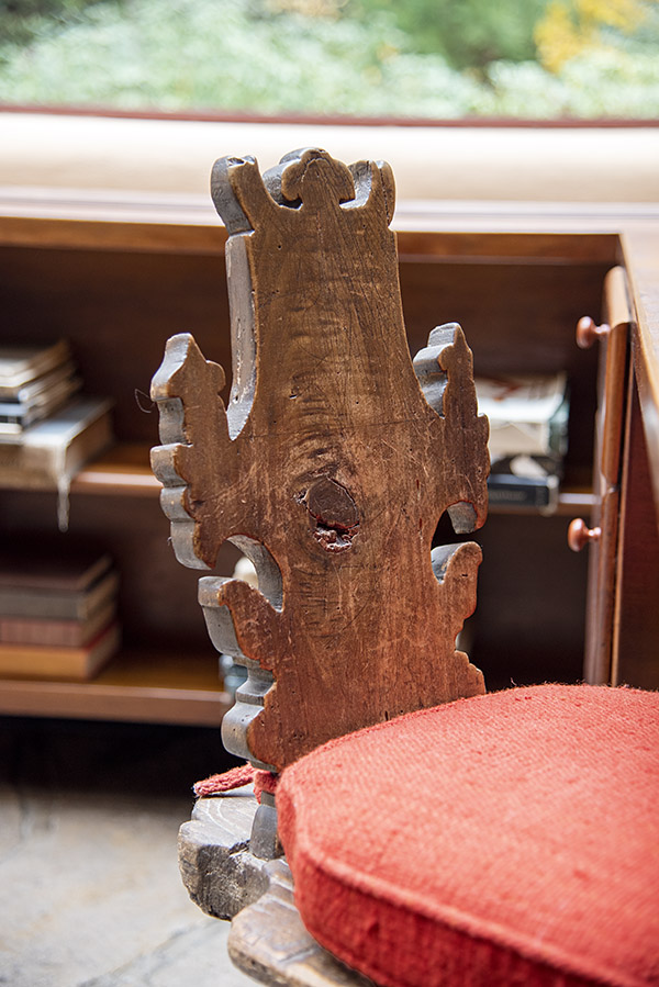
The Kaufmans asked Wright to use natural materials from the area and he did. Much of the home is constructed of local sandstone. They also asked Wright to design the interior furnishings and decor. It all works well together.
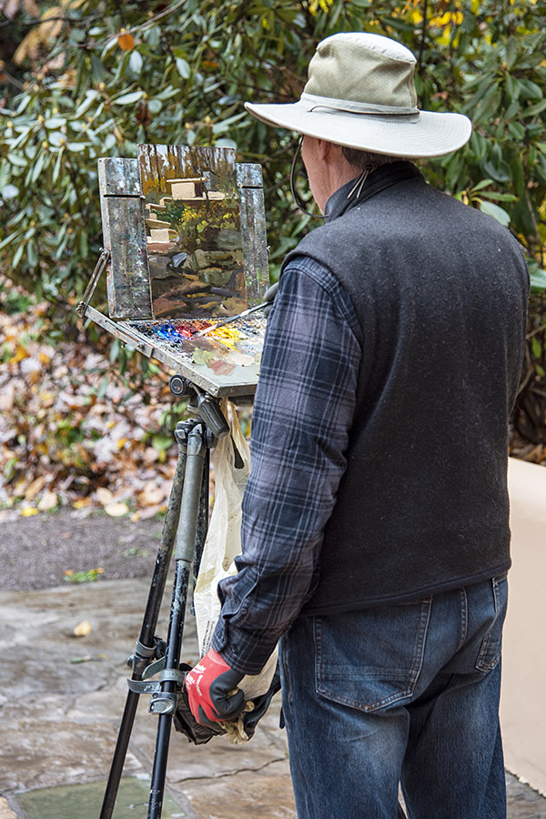
A local artist taking it all in.Wright also designed the interior and its furnishings.The family room.Wright chotchkas.Furniture crafted from local trees.More interior pieces.This looks southwestern, but it works with the sandstone walls.
In 2019, Fallingwater was added to the UNESCO World Heritage List. It is also a National Historic Landmark, it is a Commonwealth of Pennsylvania Treasure, the American Institute of Architects named it the best all time work of American Architecture. All that’s great, but take it from us, the ride and the place are awesome. As a destination, Fallingwater is tough to beat.
A photo from the exterior, showing the balconies and the surrounding woodlands.
Fallingwater is in the Laurel Highlands area about 70 miles outside of Pittsburgh. It’s a mountainous area, and because of that, the roads are perfect for great riding. The scenery, the roads, and the riding in this area are pretty much what good motorcycle riding is all about in all but the winter months. Fall is one of the best times to take it in as the leave turning colors add a further visual treat to what is already a delight to the senses. The trick is to do it late enough in the year that the leaves are turning, but not so late that the temps are too low or the roads are too icy. We were lucky; our timing was perfect.
You can’t just show up at Fallingwater. You have to make a reservation and pay for your tickets online. Trust me on this: The tour is money well spent.
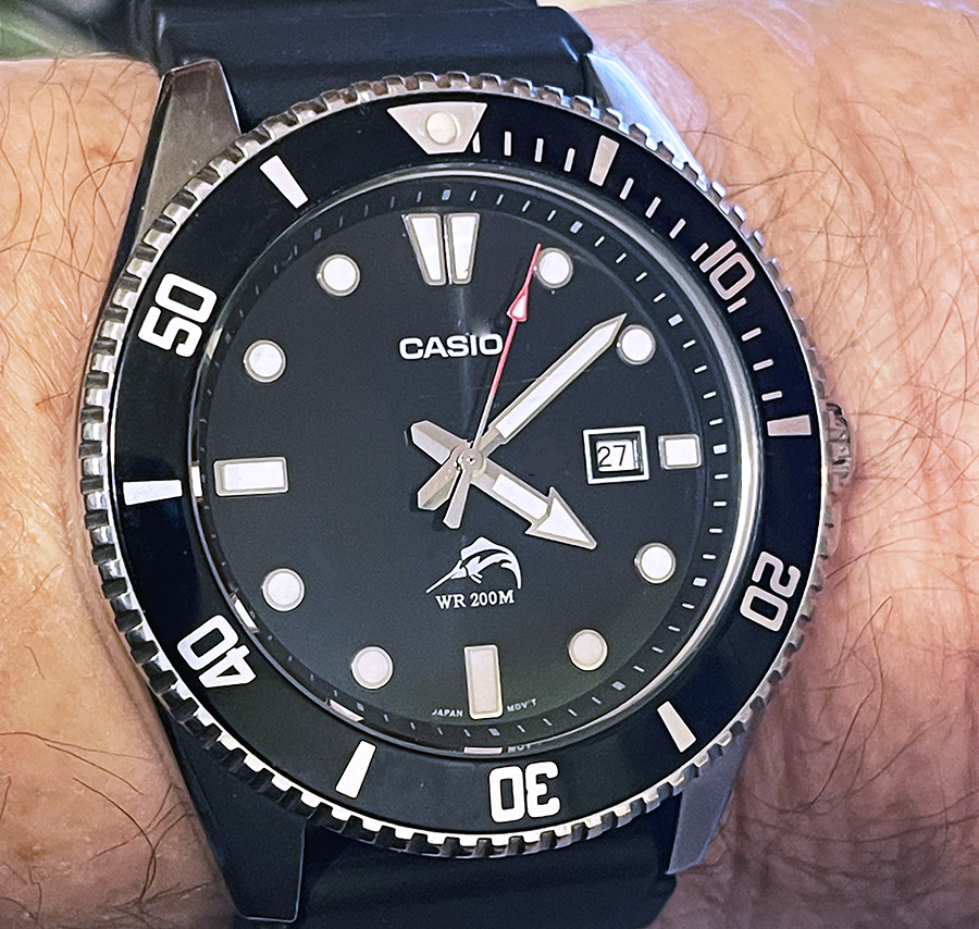
I’ve mentioned my Casio Marlin (also known as the Duro) a few times in previous blogs. I love this watch for any number of reasons: It’s accurate, it’s rugged, it’s waterproof, it’s comfortable, and it’s inexpensive. It’s a diver’s watch, but I’m not a diver. I just like the look of thing. I’ve worn it on a few big moto trips including the ride around the Andes Mountains in Colombia. It poured cats and dogs on that trip. The Marlin was unfazed.
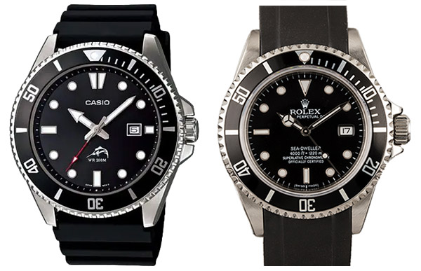
At about $50, this watch has to be the deal of the century. Just for grins I grabbed a picture of the Rolex Sea Dweller and put it along side the Casio. If you own a Rolex don’t get your shorts in a knot ((I own one, too). But the comparison has to make you wonder: Let’s see, $50 for the Casio and $16,500 (or whatever it is these days) for the Sea Dweller (if you can find one and in today’s market that’s not easy). As Aristotle would say….hmmmmm.
Yeah, you can go a little deeper with the Rolex (they say down to 3,900 meters). My Casio says it’s good for 200 meters. That’s over 600 feet down. It’s not likely I’ll ever visit those regions and if I ever do I can guarantee you the time of day is not what will be on my mind.
I’ve owned my Marlin for about 10 years now. I think I’ve had to replace the battery twice. My guy charges me $3.25 to install a new battery (parts and labor). The strap got stiff and cracked, so I’ve replaced that once (I think it was $10). I checked and the cost of a replacement resin Rolex band is close to $300. On the other hand, the Rolex is self-winding, so it never needs a battery. Again….hmmmm.
You know what to do…click on the popup ads!
On that comfort thing…the Casio Marlin is about the right size for a man’s watch and the resin band is very comfortable. I always forget I have it on and on more than a few occasions I’ve gone into the water wearing it (swimming, showering, and most recently, almost being swept away in my Subaru going to the gun club). It doesn’t matter to the Casio. I’d say it’s indestructable, but some Internet weenie would want to get into a urinating contest about that.
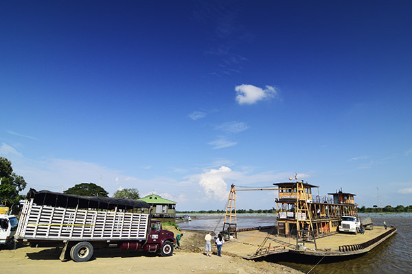
Boarding the ferry in Magangué on the Magdelena River. Even there, the Casio’s good looks and functionality appealed to an onlooker.
When I rode Colombia with Juan and Carlos, one time we had to wait a couple of hours on a hot and humid afternoon for the ferry to come in and carry us down the Magdalena River to Mompos. While we were waiting in what little shade we could find in Magangué, a young Colombian boy came over and touched the Casio, nodding his approval. If I had another watch with me I would have given it to him. I still think about that on occasion and wish I had given it to that kid. I think when I bought my Marlin, they were $39. That young fellow most likely would have cherished the Casio the rest of his life (as I will). Maybe I need another ride in Colombia. If I go again I’ll throw an extra Marlin in one of the panniers. You know, just to be prepared.
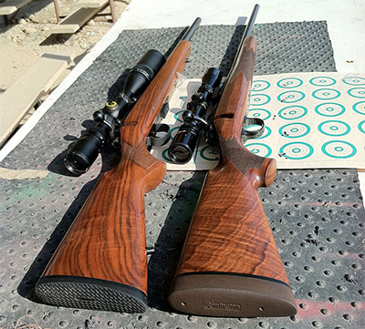 A Tale of Two .22s (a CZ Model 452 and a Remington Model 504)