The Apache Main Rotor Blade Failures

By Joe Berk

Like that photo you see above?  Yeah, me, too.  I took it on the parade grounds at Fort Knox, Kentucky, a few years ago.   I used to run the Composite Structures plant that made rotor blades for the Apache helicopter.  It was one of the best jobs I ever had.

We recently reposted (under the Wayback Machine banner) our blog about the Gator mine system, and in it I promised to write about the Apache main rotor blade failures.  This is another defense industry failure analysis war story that crosses company lines and supplier/customer boundaries, and I’m not entirely sure that there wasn’t some nefarious behavior going on at McDonnell Douglas.  I’ll tell you what happened and you tell me.

The UH-1 Huey was a Vietnam War workhorse. It was extremely susceptible to small arms fire and you could hear it coming miles away.

During the Vietnam War, the Army (my alma mater) found that the Huey helicopter had a few shortcomings.  I guess that’s to be expected; it was the first time the Army used helicopters in a major way in a real war.  The Huey was susceptible to small arms fire (and big arms fire, too, for that matter) and it was noisy.  On a clear night, you could hear a Huey coming in from a long way out with its characteristic “wop wop wop” signature as it beat the air into submission.  That “wop wop wop” sound was actually the rotor tips breaking the sound barrier on the left side of the helicopter, so the Army knew it had to do something to get the blade tip speed below the speed 0f sound on its next-gen helicopter.  Another big problem was small arms fire; a single .30-caliber AK-47 bullet through a Huey rotor blade would destroy the blade’s structural integrity (and there were a lot of AK-47 rounds in the air in those days).  When that happened, the helicopter and its crew were lost.  There could be no autorotation (you can’t autorotate without a blade) and you couldn’t bail out.  The next-gen helicopter blades would have to be impervious to small arms fire.

Fixing the blade tip speed problem was simple.  Instead of having two blades like the Huey, the Apache went to four blades.  That cut the rotor speed and let the blade tips go subsonic.  “Wop wop wop” no more.  Easy peasy.

The structural integrity issue was the more significant challenge. The engineers at McDonnell Dougas (the Apache prime contractor) designed a blade that had four spars that ran longitudinally (with the length of the blade) contructed of AM455 stainless steel (a special blend used on the Apache and, at the time, nowhere else).  The spars had overlapping epoxy-bonded joints that ran the length of the blade.  The idea was that a hit anywhere on the blade (up to and including a 23mm high explosive Russian anti-aircraft round, roughly the explosive equivalent of a hand grenade) would damage that spar, but the remaining three spars would hold the blade together.   It worked.  An Apache blade actually took a blade hit from an Iraqi ZSU-23/4 and made it back to base.

A cross section of the McDonnell Douglas Apache blade showing the four spars.

So here’s the problem:  The Army specified a blade life of 2200 hours (blades on a helicopter are like tires on a car…they wear out), but our blades were only lasting about 800 hours before the blades’ bondline epoxy joints holding the spars together starting unzipping.   It wasn’t a catastrophic failure (the helicopter could still fly home), but the blades had to be repaired.  The Army would send the blades back to McDonnell Douglas, and McDonnell Douglas sent them back to us at Composite Structures for refurbishment.  If they couldn’t be repaired, we sold McDonnell Douglas a new blade (back in the 1990s, each blade cost just north of $53,000, and McDonnell Douglas put a hefty markup on that when they sold the blade to the Army).  When they could be repaired, we still charged a hefty fee.

When I entered the picture as the plant manager, I learned that both Composite Structures (my company) and McDonnell Douglas (my customer) had made half-assed efforts to fix the blade problem, but neither company was financially motivated to eliminate it.  We were making good money selling and repairing blades and so was McDonnell Douglas.   The Army, however, was taking it in the shorts.

This was also a major problem for me as the manufacturing guy.  I didn’t like having to make two blades to get one good one.  We were rejecting one of every two blades we made for spar disbonds in the factory.  You read that right:  We had to make two blades to get one good one.  Because of this, we were in a severe past due delivery condition, and my mission was to correct that situation.  So we went to work on solving the problem.  We found and fixed plenty of problems (blade cure profile issues, cleanroom assembly shortfalls, epoxy shelf life and pot life issues, nonconforming components issues, and contamination issues), but the blade disbonds continued.  McDonnell Douglas continued to pound us for quality issues, all the while secretly smiling all the way to the bank as they continued to sell twice as many blades as they should have been selling.

We went through everything and finally concluded that there had to be a design issue with the blades; specifically, that the bondline width where the spars were glued together had too much variability.  If that glue line was small enough, we reasoned, it wouldn’t hold up and the blade would disbond.  We asked McDonnell Douglas about that (McDonnell Douglas was responsible for the design; we were building it to their engineering drawings), but they kept blowing us off.  The bondline width wasn’t dimensioned on the McDonnell Dougas drawings.  The other parts were, and McDonnell Douglas’ idea was that if the blade parts met their drawing requirements, the bondline width would be okay.   That’s what they hoped for, anyway.  But you know what they say about hope.  You can poop in one hand and hope in the other, and see which one fills up first.

A macro shot of the bondline joint. The scribe lines (in the blue Dykem) show the bondline area.

I asked for a meeting with our company and McDonnell Douglas on the blade failures, and they wouldn’t meet with us.  So I sent out another invitation, and this time I included the Army.  McDonnell Douglas was livid when the Army quickly said yes; now, the McDonnell Douglas wizards had to meet with us on this issue.  That meeting started about like I expected it to, with McDonnell Douglas tearing us a new one on the blade failures, telling us our quality was terrible, and basically letting me and the rest of the world know that, in their opinion, things had gone downhill since I had taken over as plant manager (no matter that this 50%-rejection-rate blade issue had existed for a dozen years prior to my arrival).  I patiently explained the issues we had found and corrected, and then emphasized that the problem with blade separations had continued unabated.  I then asked the McDonnell Douglas program manager about the bondline width and the fact that this apparently critical requirement was not on their engineering drawings.  He denied it was the issue and went off about our poor quality again.  When he ran out of steam, I asked the question about the bondline dimension yet again, and specifically, how narrow the bondline could be and still provide an adequate joint.  There were more accusations about our lousy quality (the guy only knew one tune and he loved singing it), and I again waited for him to finish.  When I asked the question a third time, before McDonnell Douglas lit up about our poor quality again the Army representative asked “yeah, how narrow does it have to be before the blade fails?”

The McDonnell Douglas guy stared at me like cobra looks at a mongoose (I’ve only seen this in YouTube videos, but I’m pretty sure the analogy is a good one).  He sputtered and stammered and I think I saw a little spit fly from his mouth.  “If you make it to the drawing it will be okay,” he said.  I mean, under the circumstances it was the only thing he could say.  I almost felt sorry for him, in the same way you feel sorry for a rat when a red-tailed hawk is swooping down with talons extended.  You feel bad, but you look forward to seeing the hawk doing his thing.

The Army guy sensed this was something big. “How low?” he asked again.  If there is such a thing as a perfect impersonation of a deer caught in the headlights, the McDonnell Douglas dude was nailing it.  It was what we in the literary world call a pregnant pause, one of those “what did the President know, and when did he know it?” moments.  As I type this, I can remember the scene like it happened 10 minutes ago, but it’s been close to 30 years.

“0.375 inches,” the McDonnell Douglas dude finally answered.  He actually said the zero in a half-assed attempt to add engineering gravitas to his answer. “As long as they build it to the print, they’ll be okay,” he added, with a “so there” smirk.  He was answering the Army man, but the smirk was all for me.

What the McDonnell Douglas guy didn’t know was that my guys could see the bondline width in an x-ray, and we x-rayed every blade returned for repair.  And I guess he didn’t realize how easy it was to do a tolerance analysis to show what the drawings allowed the bondline width to be.

What happened next was one of those moments I’ll remember for the rest of my life.  I looked my engineering guy and my QA guy.  They knew what I wanted.  They both left the room.  Fifteen minutes later they were back.   My engineering guy handed me the results of his tolerance analysis.  The McDonnell Douglas engineering drawings tolerance stackups allowed the bondline width to go as low as 0.337 inch.   The QA guy had even better information.  All the blades that had been returned to us for spars unzipping (which was the only reason we ever saw a blade returned) had bondline widths less than 0.375 inches (McDonnell Douglas’ admission for the lower limit) but above .337 inches.  In other words, our quality was fine.  The failed blades met the McDonnell Douglas engineering drawings but were below the value I had finally prodded McDonnell Douglas into revealing.

I could have been more diplomatic, I guess, but that wasn’t me.  I shared that information with the room.  The Army rep smiled.  “I think you guys might want to continue the meeting without me,” he said.  And then he left.

The McDonnell Douglas guy exploded as soon as the door closed.  He was apoplectic (I looked that word up; it means overcome with anger and extremely indignant, and that was him).  McDonnell Douglas had been screwing the Army for years with a deficient design and now it was out in the open.  They were potentially exposed to defective design claims from the Army (and from us) for hundreds of millions of dollars.  Think about it:  12 years of Apache blade production, a 50% failure rate in production, a blade life of only 800 hours (against the Army’s spec requirement of 2200 hours), and the fact that we and McDonnell had factored all that waste into our pricing.

Fortunately for McDonnell Douglas, the Army wasn’t interested in suing them (all they wanted was good blades).   My boss wasn’t interested in pursuing a claim against McDonnell Douglas, either, as they were our bread and butter and he wanted to keep the business.  We fixed the problem by holding the blade components to tighter tolerances (tighter than McDonnell Douglas had on their drawings) so the bondline width would always be above the magical 0.375 inch, and we never had a blade unzip in production again.  McDonnell Douglas did not correct their drawings, as it would have been an admission of guilt on their part that would absolutely guarantee a loss if the Army ever took them to court.

So there you have it:  The Apache main rotor blade failures, all caused by sloppy engineering at McDonnell Douglas.  It’s hard to believe that the blades had a 50% failure rate and didn’t meet the Army’s specified blade life for a dozen years before the problem was fixed, but that’s what happened.  It’s also hard to believe that nobody at McDonnell Douglas went to jail for it.


Never miss an ExNotes blog:

An Unfired NIB Liberty Model 77

By Joe Berk

The Ruger Model 77 rifle goes back to 1968.  It gave Ruger a place in the centerfire hunting rifle class, and like the Remington Model 700 and Winchester Model 70 it would compete against, it outdid both by using the lucky number 7 twice in its name.  The Model 77 is a good-looking bolt action rifle based on the Mauser design, with a classic walnut stock designed by famed custom rifle builder Lenard Brownell.  I’ve owned several Model 77 Rugers, including this new-in-the-box .30 06 Liberty gun.  I’d like to be able to tell you how accurate it is, but I can’t.  I’ve never fired it.  Nor has anyone else, other than the person who test fired it before it left the factory.

Every firearm Ruger manufactured in 1976 carried this inscription.
There’s no lawyer’s warning on the barrel about reading the instructions. We call these “pre-warning” guns. They were made in a time when people had more common sense.

The Liberty designation mentioned above refers to the “Made in the 200th Year of American Liberty” roll marking on the barrel, which was a feature Ruger had on all its guns made in 1976.  I bought the rifle in El Paso that year (I was in the Army stationed at Fort Bliss).  This one has every thing that came with the rifle (the original serial numbered box, the scope rings and their blue cloth bag, the instructions, and the warranty card).  It’s a brand new, unfired, almost-50-year-old rifle.

The tang safety Model 77 is considered more desireable.
The original box. The cardboard held up surprisingly well. This gun is new in the box (NIB) and this is the original box.
Original documents!

The box is serialized to the rifle. I obliterated the last number, which almost makes it look like the serial number matches the chambering.

You know, Rugers (and most guns, for that matter) were different 50 years ago.  The bluing was deeper, the checkering was hand cut (and way better than the laser cut fuzzball checkering you see today), and the guns just felt better.   This Ruger is like that.  It’s immaculate, and there’s only safe ding on the stock.  Other than than, there’s not a mark, dent, ding, gouge, scratch, or (Heaven forbid) spot of rust anywhere on the rifle.  Even the anodized aluminum floorplate is pristine.

The Ruger Model 77 MSRP was $169.50 in 1976 and I believe I paid something like $139 for this one.  I probably have the original receipt for it somewhere.   A new Ruger Hawkeye in .30 06 (the rifle the Model 77 evolved into) lists for $1399 (yep, ten times what I paid in 1976), but a new one is not as cool as the one you see here.

Plain walnut, but elegant in its own way.
The unmarred anodized aluminum floorplate.
Early Ruger Model 77s wore this grip cap.
Check out this gorgeous hand cut checkering. You don’t see that too much today!
The rifle’s sole safe ding, done by yours truly. Nobody’s perfect.  It will steam out.  I’m leaving it like this.
God’s cartridge. The .30 06 is one of the all time greats.

This rifle may be going on the block soon.  It’s time to start downsizing the armory and it’s time for someone else to enjoy owning it.  You’re probably wondering how much I’m going to ask for it.  So am I.  As I look at this magnificent example of 1970s firearm manufacturing and post these photos, I’m having second thoughts.  It is a .30 06, and that’s God’s cartridge.  Maybe it needs to send a few rounds downrange, and maybe I’m the guy to do it.  We’ll see.


Never miss an ExNotes blog:


More Tales of the Gun!

Dream Bikes: The Honda Dream

My Dad and I saw our first Honda ever in 1964 at a McDonald’s in East Brunswick, New Jersey.  It was a 150cc Dream, the smaller version of the bigger CA 77 305cc Dream.  I was 12 years old at the time.  In those days, it was a fun family outing to drive the 20 miles to Route 18 in New Jersey and have dinner at McDonald’s (that was the closest one), where hamburgers were 15 cents and the sign out front said they had sold over 4 million of the things. And the Honda we saw that day…Dad and I were both smitten by the baby Dream, with its whitewall tires, bright red paint, and the young clean cut guy riding it.  True to Honda’s tagline, he seemed to be one of the nicest people you could ever meet (although admittedly the bar wasn’t very high for nice people in New Jersey).


Keep us in clover…please click on the popup ads!


Dad and I started looking into Hondas, and that included a trip to Cooper’s Cycle Ranch near Trenton.   Back then, it really was a ranch, or at least a farm of some sort…the showroom was Sherm Cooper’s old barn.  The little Hondas were cool, but the big ones (the 305s) were even cooler. A 305 was the biggest Honda available in the mid-1960s and Honda imported three 305cc motorcycles to America:  The CA 77 Dream, the CB 77 Super Hawk, and the CL 77 Scrambler.  The Dream was not designed to be an off road motorcycle (that was the CL 77 Scrambler’s domain) or a performance motorcycle (in the Honda world, that was the CB 77 Super Hawk).

Of the 305 twins,  It’s probably appropriate to discuss the CA 77 Dream first.  The Scrambler and the Super Hawk were intended to appeal to motorcycle enthusiasts; the Dream was a much less intimidating ticket in (into the motorcycle world, that is).  The typical Dream buyer was either someone stepping up from a smaller Honda, or someone who had not previously owned a motorcycle.

Honda first used the name “Dream” on its 1949 Model D (a single cylinder, 98cc two-stroke).  No one knows for sure where the Dream moniker came from, but legend has it that someone, upon first seeing the Model D, proclaimed it to look like a dream.  The C-series Dreams first emerged in Japan in 1957.  Pops Yoshimura built Honda engines with modified production parts that ran over 10,000 rpm for 18-hour endurance races, proving the basic design was robust.  Some say Honda based the engine design on an earlier NSU engine, but Honda unquestionably carried the engineering across the finish line.  Whatever.  When’s the last time you saw an NSU?  Another big plus was that Honda used horizontally split cases and that (along with vastly superior quality) essentially eliminated oil leaks.  The other guys (and in those days, that meant Harley and the Britbikes) had vertically split cases and they all leaked.  Honda motorcycles did not, and that was a big deal for a motorcycle in the 1960s.

There were several differences between the Dream and the other two Honda 305cc motorcycles.  The Super Hawk and the Scrambler had tubular steel frames and forks; the Dream used pressed steel for both its frame and fork.  The Dream was a single-carb motorcycle; the Super Hawk and the Scrambler had twin carbs.  The Dream had large steel valanced fenders, the other Hondas had more sporting abbreviated fenders.  The Dream was the only 305 that came from the Honda factory with whitewall tires.  The Dream had leading link front suspension; the Scrambler and the Super Hawk had telescopic forks.   The Dream used the Type II crankshaft (so did the Scrambler) with a 360-degree firing order (both pistons went up and down together, but the cylinders fired alternately).   The higher performance Super Hawk had the Type I, 180-degree crankshaft.  Like the Super Hawk, the Dream had electric starting (the Scrambler was kick start only).  The Dream came with a kickstarter, too, but why bother?  I mean, you weren’t going to be mistaken for Marlon Brando when you rode a Honda Dream.

The Dream’s 305cc engine had a single 23mm Keihin carb and it produced 23 horsepower at 7500 rpm (not that the rpm was of any interest; the Dream had no tachometer).  With its four-speed transmission and according to magazine test results, the Dream was good for between 80 and 100 mph (depending on motojournalist weight, I guess).  The Dream averaged around 50 mpg, although in those blissful days of $0.28/gallon gasoline, nobody really cared.   Honda Dreams came in white, black, red, or blue.  With 20/20 hindsight, I wish I had bought one in each color and parked them in the garage.  My favorites were black or white; those colors just seemed to work with the Dream’s whitewall tires.

Honda built the Dream until 1969.  The Dream retailed for $595 back in those days, but a shrewd negotiator could do better.


Never miss an ExNotes blog:


See our other Dream Bikes here!

The Wayback Machine: Later, Gator…

By Joe Berk

I had a tough time choosing a title for this blog.  I went with what you see above because it reminds me of one of my favorite Dad jokes…you know, the one about how you tell the difference between a crocodile and an alligator.  If you don’t see it for a while, it’s a crocodile.  If you see it later, well, then it’s a gator.  The other choice might have been the old United Negro College Fund pitch:  A Mine is a Terrible Thing to Waste.  But if I went with that one I might be called a racist, which seems to be the default response these days anytime anyone disagrees with anyone else about anything.

Gresh likes hearing my war stories.  Not combat stories, but stories about the defense industry.  I never thought they were all that interesting, but Gresh is easily entertained and he’s a good traveling buddy, so I indulge him on occasion.  Real war stories…you know how you can tell them from fairy tales?  A fairy tale starts out with “once upon a time.”  A war story starts out with “this is no shit, you guys…”


Don’t forget to click on the popup ads…it’s how we get paid and how we keep the blog alive.


So, this is a “no shit” story.  It sounds incredible, but it’s all true.  I was an engineer at Aerojet Ordnance, and I made my bones analyzing cluster bomb failures.  They tell me I’m pretty good at it (I wrote a book about failure analysis, I still teach industry and gubmint guys how to analyze complex systems failures, and I sometimes work as an expert witness in this area).  It pays the rent and then some.

So this deal was on the Gator mine system, which was a real camel (you know, a horse designed by a committee).  The Gator mine system was a Tri-Service program (three services…the Army, the Navy, and the Air Force).  It was officially known as the CBU-89/B cluster munition (CBU stands for Cluster Bomb Unit).  The way it worked is instead of having to go out and place the mines manually, an airplane could fly in and drop a couple of these things, the bombs would open on the way down and dispense their mines (each cluster bomb contained 94 mines), the mines would arm, and voila, you had a minefield.  Just like that.

It sounds cool, but the Gator was a 20-year-old turkey that couldn’t pass the first article test (you had to build two complete systems and the Air Force would drop them…if the mines worked at a satisfactory level, you could start production).  The UNCF slogan notwithstanding, the folks who had tried to take this Tri-Service camel and build it to the government’s design wasted a lot of mines.  In 20 years, several defense contractors had taken Gator production contracts, and every one of them failed the first article flight test.  When my boss’s boss decided we would bid it at Aerojet, I knew two things:  We, too, would fail the first article flight test, and it would end up in my lap.  I was right on both counts.  We built the flight test units per the government design and just like every one else, we failed with a disappointing 50% mine function rate.  And I got the call to investigate why.

So, let’s back up a couple of centuries.  You know, we in the US get a lot of credit for pioneering mass production.   Rightly so, I think, but most folks are ignorant about what made it possible.  Nope, it wasn’t Henry Ford and his Model T assembly line.   It was something far more subtle, and that’s the concept of parts interchangeability.  Until parts interchangeability came along (which happened about a hundred years before old Henry did his thing), you couldn’t mass produce anything.  And to make parts interchangeable, you had to have two numbers for every part dimension:  The nominal dimension, and a tolerance around that dimension.  When we say we have a 19-inch wheel, for example, that’s the nominal dimension.  There’s also a ± tolerance (that’s read plus or minus) associated with that 19-inch dimension.  If the wheel diameter tolerance was ±0.005 inches, the wheel might be anywhere from 18.995 to 19.005 inches.  Some tolerances are a simple ± number, others are a + something and a – something if the tolerance band is not uniform (like you see in the drawing below).  But everything has a tolerance because you can’t always make parts exactly to the nominal dimension.

Where companies get sloppy is they do a lousy job assigning tolerances to nominal dimensions, and they do an even worse job analyzing the effects of the tolerances when parts are built at the tolerance extremes.  Analyzing these effects is called tolerance analysis.  Surprisingly, most engineering schools don’t teach it, and perhaps not so surprisingly, most companies don’t do it.  All this has been a very good thing for me, because I get to make a lot of money analyzing the failures this kind of engineering negligence causes.  In fact, the cover photo on my failure analysis book is an x-ray of an aircraft emergency egress system that failed because of negligent tolerancing (which killed two Navy pilots when their aircraft caught fire).

I don’t think people consciously think about this and decide they don’t need to do tolerance analysis.  I think they don’t do it because it is expensive and in many cases their engineers do not have the necessary skills.  At least, they don’t do it initially.  In production, when they have failures some companies are smart enough to return to the tolerancing issue.  That’s when they do the tolerance analysis they should have done during the design phase, and they find they have tolerance accumulations that can cause a problem.

Anyway, back to the Gator mine system.  The Gator system had a dispenser (a canister) designed by the Air Force, the mines were designed by the Army, and the system had an interface kit designed by the Navy.  Why they did it this way, I have no idea. It was about as dumb an approach for a development program as I have ever seen.  Your tax dollars at work, I guess.

The Navy’s Gator interface kit positioned the mines within the dispenser and sent an electronic pulse from the dispenser to the mines when it was time to start the mine arming sequence.  This signal went from coils in the interface kit to matching coils in each mine (there was no direct connection; the electric pulse passed from the interface kit coils to the mine coils).  You can see these coils in the photo below (they are the copper things).

In our first article flight test at Eglin Air Force Base, only about 50% of the mines worked.  That was weird, because when we tested the mines one at a time, they always worked.  I had a pretty good feeling that the mines weren’t getting the arming signal.   The Army liked that concept a lot (they had design responsibility for the mines), but the Air Force and the Navy were eyeing me the way a chicken might view Colonel Sanders.

I started asking questions about the tolerancing in the Navy’s part of the design, because I thought if the coils were not centered directly adjacent to the matching coils in each mine, the arming signal wouldn’t make it to the mine.  The Navy, you see, had the responsibility for the stuffing that held the mines in place and for the coils that brought the arming signal to the mines.

At a big meeting with the engineering high rollers from all three services, I floated this idea of coil misalignment due to tolerance accumulation.  The Navy guy basically went berserk and told me it could never happen.  His reaction was so extreme I knew I had to be on to something (in a Shakespearian methinks the lady doth protest too much sort of way).  At this point, both the Army and Air Force guys were smiling.  The Navy guy was staring daggers at me.  You could almost see smoke coming out his ears. He was a worm, I was the hook, and we were going fishing.  And we both knew it.

I asked the Navy engineer directly how much misalignment would prevent signal transmission, he kept telling me it couldn’t happen, and I kept pressing for a number:  How much coil misalignment would it take?  Finally, the Navy dude told me there would have to be at least a quarter of an inch misalignment between the Navy coils and those in the mine.  I don’t think he really knew, but he was throwing out a number to make it look like he did.  At that point, I was pretty sure I had him.  I looked at my engineering design manager and he left the room.  Why?  To do a tolerance analysis, of course.  Ten minutes later he was back with the numbers that showed the Navy’s interface kit tolerances could allow way more than a quarter inch of misalignment.

When I shared that with the guys in our Tri-Service camel committee, the Navy guy visibly deflated.  His 20-year secret was out.  The Army and the Air Force loved it (they both hated the Navy, and they really hated the Navy engineer).

We tightened the tolerances in our production and built two more cluster bombs.  I was at the load plant to oversee the load, assemble, and pack operation, and when we flight tested my two cluster bombs with live drops from an F-16 we had a 100% mine function rate (which had never been achieved before).  That allowed us to go into production and we made a ton of money on the Gator program.  I’m guessing that Navy weasel still hates me.

It’s hard to believe this kind of stuff goes on, but it does.  I’ve got lots of stories with similar tolerance-induced recurring failures, and maybe I’ll share another one or two here at some point.  Ask me about the Apache main rotor blade failures sometime…that’s another good one and I’ll post a blog about it in the next week or so.

Stay tuned, my friends.


Never miss an ExNotes blog:

The Wayback Machine: Marking Time

By Joe Berk

I’ve always been a watch guy. It probably started when my parents surprised me with a Timex when I was a kid. The thought of having my own wristwatch was heady stuff for a boy back on the east coast (or anywhere else, I imagine). To make a long story short, I’ve been a watch collector ever since. I don’t specialize, and many times I won’t keep a watch forever. If I like the way a watch looks and it’s not crazy expensive, I’ll wear it for a while, with the duration of “a while” usually determined by the time it takes for the next interesting thing to catch my eye.

The real deal: Apollo 15 Astronaut Dave Scott’s Bulova, which sold for a cool $1.625 million at auction.

I make no excuses: I like watches, and I always wonder about guys who don’t wear them. Not wearing a watch is a common thing with young guys today. When I taught in Cal Poly’s College of Engineering, one of my topics focused on how to do well in an interview. My guidance was simple. Dress sharply, be early, look the interviewer right in the eye, speak up, don’t use the word “like” incessantly when you speak, and wear a watch. A lot of kids today don’t wear watches. If they have any interest in knowing what time it is, they look at their iPhone. That’s a no go, I’d tell my students. If you don’t wear a watch, the person interviewing you will conclude you have no sense of time-based urgency. It’s what I always concluded when someone showed up not wearing a watch.

Anyway, to get to the subject of this blog, I want to tell you about the Bulova Lunar Pilot. It’s a cool piece with an interesting story that goes like this: With the advent of the Apollo lunar exploration program (the NASA endeavor to put men on the moon), the US government decided we needed an official space watch. Omega won the competition with their Speedmaster watch, and for the next 14 missions, that’s what astronauts wore.

Here’s where it gets complicated and where the story gets Internet-fuzzy. Depending on which source you believe, Astronaut Dave Scott wore a Bulova watch on the Apollo 15 mission for one of the following reasons:

He wore the Bulova watch because his Omega broke.
He wore the Bulova watch because he felt like it.
He wore the Bulova watch because Bulova was trying to replace Omega as the official NASA watch.
He wore the watch because the US government, Bulova, or other parties wanted the official watch to be something made in America.

Whatever the reason (and you can find stories supporting each of the above floating around in that most authoritative of all sources, the Internet), Dave Scott wore the Bulova on the Apollo 15 mission, and Omega went from being “the only watch worn on the moon” to “the first watch worn on the moon.” It could not have gone over well at the Omega factory.

Dave Scott’s original Bulova, the one he wore on the moon, sold at auction a few years ago. The predicted auction price was $50,000. As predictions go, it wasn’t a very good one. When the gavel came down and the dust cleared, Scott’s Bulova sold for a cool $1.3 million. Throw in the auction commission and other fees, and you’re talking about a $1.625-million wristwatch. Wowee!

Bulova, today no longer an American watch company (they were bought by Citizen a few years ago) recognized a marketing opportunity when it fell into their laps, and they re-issued an internally updated version of Scott’s watch as the Bulova Lunar Pilot, complete with a 262 kHz Accutron movement. I have no idea what a 262 kHz movement is, except that the Bulova marketing hype tells me it means it’s super accurate.

The not-so-real deal, but a hell of a deal nonetheless: The Bulova Lunar Pilot, purchased for just under $300.  Yep, as I type this, I’m wearing my Bulova.

The increased accuracy really didn’t matter to me when I saw the watch (I’m retired now and I seldom need 262 kHz accuracy when I decide I feel like going somewhere), so that’s not what prompted me to pull the trigger. I just like the way it looks, I like the swirl of stories around the original Bulova moon watch, and my Dad wore a Bulova when I was a kid.

Oh, one other thing helped…a trick that has prompted me to pull the trigger on other discretionary purposes.  You know how the Internet spies on us, right?  I mean, folks complain all the time about looking at something on Amazon or whatever and then it starts showing up in their Facebook feed.   That’s not always a bad thing.  When I first looked at the Bulova Lunar Pilot it was a $600 bauble.   I wasn’t going to pay that kind of money, and I guess the spymasters/Internet marketeers figured that one out.  They and I knew it was a waiting game to see who would blink first.  Because I had looked for the watch on Amazon, I started getting emails from different retailers to buy the watch for less, and I let those roll in.  Delete, delete, delete, and then one day, an offer floated into my inbox for $299.  Hmmm.  Delete.  And sure enough, a day or two later and that $299 offer came with a coupon for $20 off and free shipping on my first order.  Ka ching!


Help us bring you these stories:  Please click on the popup ads!


More watch and other reviews are here!

Lee’s Classic Turret Press and the S&W Shield: Range Results

By Joe Berk

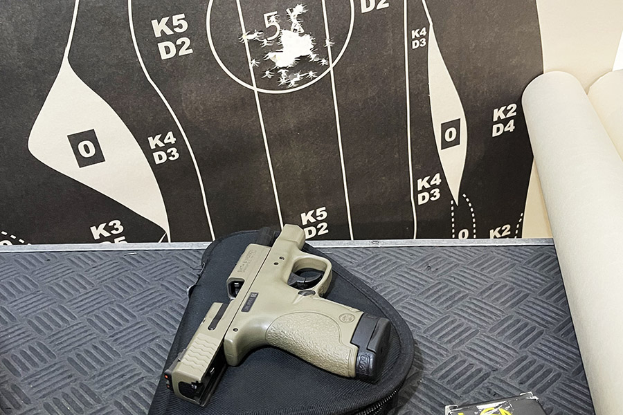
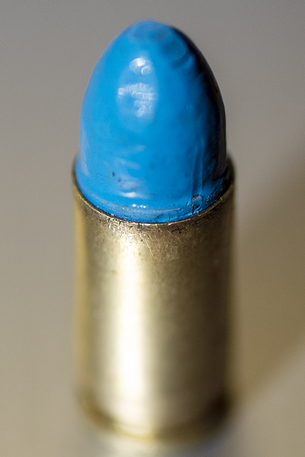
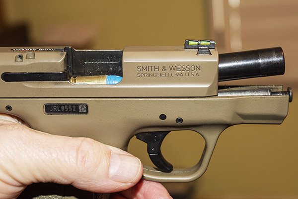
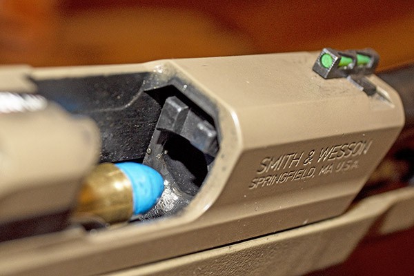
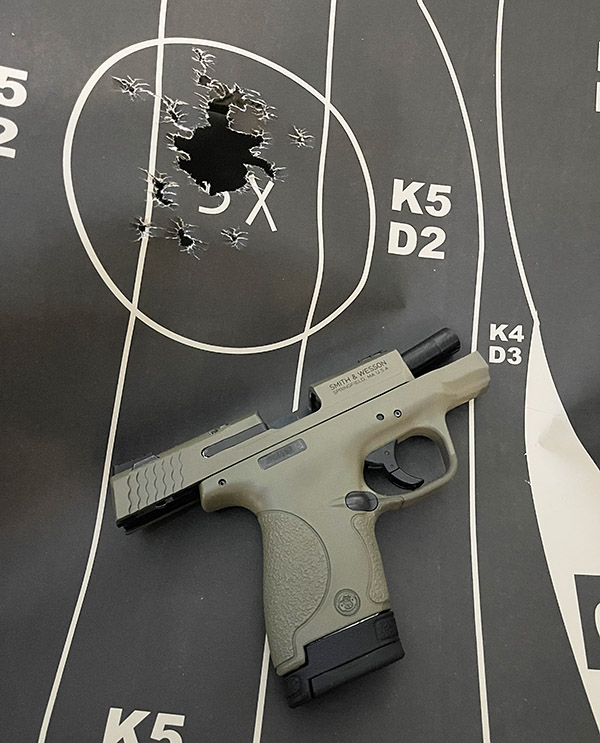
Check out that photo above.  It’s a flat dark earth Smith and Wesson M&P 9 Shield, with ammo reloaded using the Lee Classic Turret Press Kit.  Yep, this is a “two-fer” blog:  A first look at the Shield, and an evaluation of the first loads prepped with the Lee Classic Turret Press Kit.

I initially tried two loads in the Shield:

      • 124-grain plated roundnose Rainier bullets and 5.2 grains of Accurate No. 5 powder.
      • 124-grain plated roundnose Rainier bullets and 5.6 grains of Accurate No. 5 powder.

I wanted to start low and work up, partly because that’s good reloading practice and partly because the Shield was new to me and I didn’t know how it would work and what it would like.  The first reduced load (5.2 grains of Accurate No. 5 and a 124-grain plated bullet) wouldn’t cycle the Shield’s action.   I fired 50 rounds this way, one at a time.  I’d have to pull the slide back and release it after each shot.  For the Shield portion of the evaluation, I knew I needed to bump up the load.  For the ammo portion of the evaluation, every load fed and fired flawlessly.  The Lee turret press had done its job.

Bumping up to the 5.6 grains of Accurate No. 5 (still with the 124-grain plated bullet), the Shield’s action cycled but a couple of times the slide closed after the last round in the magazine fired.   I fired 50 rounds in this test, loading 5 rounds in the Shield’s magazine each time.  The Shield was pushing the slide back far enough to strip off a new round, but on two magazine loadings the slide did not go far enough  back to engage the slide stop after the last round. I needed to bump the charge a scosh more.  For the ammo eval, every load fed, fired, and ejected flawlessly.  Again, the Lee turret press had done its job.

The Lee Classic Turret Press, a phenomenal value and a great reloading setup.

At this point, I knew I needed to go a little higher on the powder charge with the 124-grain plated bullet, and I knew the Lee Classic Turret Press was making good ammo.  Everything fed and there were no jams.

The first rounds loaded to an overall cartridge length of 1.610 inches. I later moved that back to 1.140 inches.

I loaded the above 9mm ammo to an overall length of 1.160 inches, which is longer than I usually load 9mm.  The Lee manual has the cartridge overall length with a plated 124-grain Rainier bullet at 1.169 inches.  The cartridges would go in the Shield’s magazine and they fed fine when shooting, but when loading them in the magazine, the first cartridge tended to go horizontal instead of being angled up as others were loaded on top of it.  That hung up the magazine while cartridges were being loaded into it.  In the past, I had normally loaded 9mm at around 1.120 to 1.130 inches overall length.  I decided that for my next load I would go up to 5.8 grains of Accurate No. 5, and I would seat the bullets for an overall cartridge length of 1.140 inches.  I went home and in 20 minutes I had loaded another 50 rounds.  That Lee Classic Turret is fast.

50 rounds of custom-crafted 9mm ammo created on the Lee Classic Turret Press.

The popup ads keep us going…please click on them!


When I returned to the West End Gun Club, I set up a target at 50 feet, took out the Shield, and loaded the first magazine.  Loading to a cartridge overall length of 1.140 made it easier to load the magazine.  So far, so good.

Next, I fired 20 rounds to assess the ammo’s functionality.  Everything worked perfectly.  Every round fed, every round ejected, and life was good.  The Shield’s bright fixed sights were printing a bit to the left, so I held to the right on a fresh target and rattled off 30 rounds.

Thirty rounds at 50 feet from the Shield. Not too shabby for a belly gun.

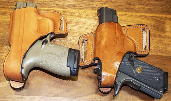
The Shield’s recoil was not at all uncomfortable; it was way better than a .38 snubnose revolver.  The Shield is a very light pistol (19.0 ounces).  That’s lighter than the S&W Model 60 (23.2 ounces) or a Compact 1911 (33.4 ounces).  Those weights for the 1911 and the Model 60 may not sound like a lot, but (trust me on this) it’s enough to weigh on you at the end of the day.  I guess the Shield’s light weight is the big advantage of a Tupperware gun.  I like it, and I like the fact that the gun is pleasant to shoot.

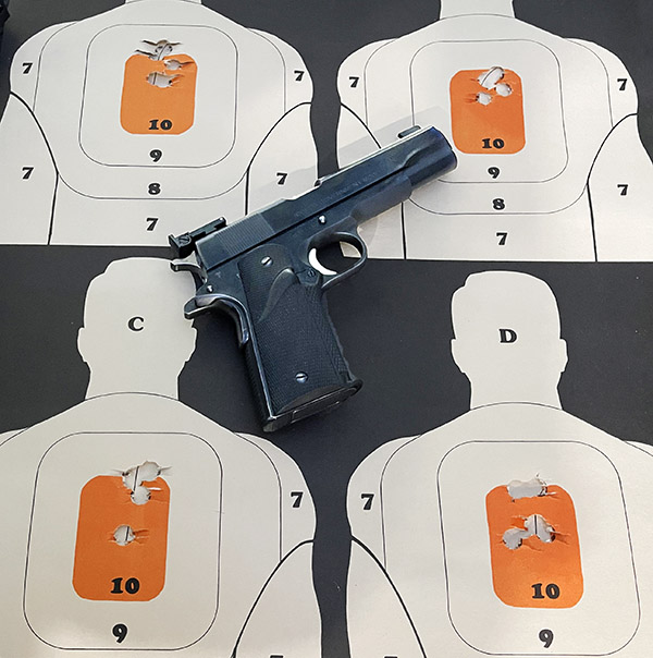
A few days later, I was on an indoor range and I set up the Alco target that has four mini-silhouettes on a single sheet.  I ran it out to 21 feet and put 50 rounds on target (dividing them roughly between the four targets), all shot offhand while standing.  The load was the same as the one mentioned above.  That’s 5.8 grains of Accurate No. 5 and a 124-grain plated Rainier roundnose bullet at an overall cartridge length of 1.140 inches, and for these, I used mixed brass.

The quad mini-silhouette from Alco Target in Monrovia, California, and 50 rounds fired standing at 7 yards.

I also tried two different powder-coated bullets with Accurate No. 5.  One was the 147-grain Boudreau flat nosed bullet with 4.8 grains of Accurate No. 5.  This is an accurate load in the Shield (even more so than the plated bullet load mentioned above), but it leaded the bore.  The other was the Boudreau 124-grain round nose bullet with 5.4 grains of Accurate No. 5; it, too, leaded the bore.  The plated bullets did not lead the bore at all so I think they are a better load.    I loaded more 147-grain powder coated bullets with a lighter charge to see if that would eliminate the bore leading, but they did not and I had cycling issues.  4.8 grains of Accurate No. 5 is what this 147-grain powder coated bullet wants.

The Shield with 124-grain powder coated roundnose bullets. These leaded the bore.
147-grain powder coated bullets. These, too, leaded the bore. They are accurate, though.
Another Alco quad mini-silhouette with 5-shot groups fired standing at 7 yards, this time with the 147-grain powder coated Boudreau bullet and 4.8 grains of Accurate No. 5.

Let’s talk about the Shield a bit.  My Shield is the first iteration (not the Shield 2.0, as that model is not sold in California).  The Shield has a 3 1/8-inch barrel.

The Shield’s 8-round magazine. The left arrow points to the spacer. It can slide up, as indicated by the right arrow.

The Shield’s magazine could be better.  It has a plastic spacer at the bottom, and that spacer rides up when loading the magazine.  Conceivably, it could interfere with seating the magazine in the gun.  In my opinion it is a poor design.  The collar slides down as easy as it slides up, so that’s good.  You get two mags with the Shield.  The one you see above holds 8 rounds and it has a grip extender that feels just right to me.  There’s another one that doesn’t have the grip extender and it holds 7 rounds.  I haven’t done anything with that one, other than checking to make sure it was in the box when I bought the gun.

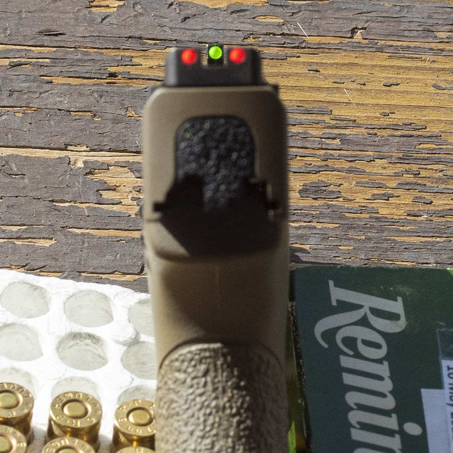
The Shield’s sights are the best I’ve ever used.  They are bright and easy to see.  The sights let in light from the sides, and that design just flat works.  It’s the first gun I have ever shot with these sights.  They are better than my SIG P226s’s Tritium sights, and those sights are good.  The photo below isn’t enhanced; it’s what the Smith’s sights actually look like.

The Shield’s sights. They are the best I’ve ever used.

The Shield’s trigger, in a word, is terrible.  There are other triggers available for the Shield, but I will leave this one alone.  The trigger got a little better with use and a couple of cleanings (I’ve put about 600 rounds through the Shield so far).  The Shield is a striker-fired gun and the trigger is not what I would consider good, but it’s better than it was initially.  Compared to a good 1911 like the Springfield, it’s awful.  But, it’s good enough to get rounds on target (as you can see above).

The Shield’s slide release, out of the box, was super stiff and essentially unusable.  I could release the slide with two thumbs, but not with one.  I found it best to pull the slide back and let it go to release the slide.  This aspect of the design (or its execution) is poor, and requiring two hands to release the slide is not good for a defensive weapon.  A close examination of the slide stop showed that it was rough where it interfaced with the slide, so I judiciously worked it over with 600-grit sandpaper, and it releases more easily now.  I can release it with one thumb with no magazine in the gun, but it still takes two thumbs and a lot of effort with the mag inserted and that’s bad.  It’s surprising that Smith and Wesson would let this happen.

A SIG P226, the Smith and Wesson Shield, and a Springfield Armory 1911, all chambered in 9mm. Flat dark earth is the new black.

I had the SIG and my 1911 with me when I shot the Shield.  The Shield doesn’t look that much smaller in a group photo, but it is flatter and it will carry concealed better.  In subsequent blogs, I’ll explore different loads prepared on the Lee Classic Turret press fired in all three of the guns above.  I fired a few rounds through the Springfield, and they worked just fine; the same is true for the SIG P226.  Interestingly, the lighter loads that wouldn’t work in the Shield did work in the Springfield.  It’s counterintuitive, but compact handguns are tougher to make work well than are full size handguns. That’s because the recoil spring in a compact handgun has to be much stiffer than one in a full size gun.

The Shield’s sear deactivation lever.  You have to push it down to remove the slide and barrel.

To takedown the Shield, you do not simply unlock the slide takedown lever. There’s a sear deactivation release in the magazine well (identified with a red arrow in the photo above), and you have to push that down before you can turn the slide takedown lever for disassembly.  You can’t do it with your finger; you need a small screwdriver or a thin pen.  With the SIG, you just turn the slide takedown lever with the slide back.

Cleaning the Shield is a breeze.  You make sure the gun is unloaded, release the mag, lower the sear deactivation lever, rotate the slide takedown lever, and the gun comes apart.  The slide comes off the frame, and the spring subassembly and barrel come out.  That’s it.  Five parts (the magazine, the receiver, the barrel, the spring subassembly, and the slide.

The plated ammo I loaded on the Lee turret press didn’t lead at all.  Zero.  Zip.  Nada.  The powder coated bullets did, which surprised me.  All were accurate.

The bottom line?  Let me put it this way: I like the Shield; I love the Lee Classic Turret Press kit.  The Shield will get better with more shooting and I want to try more loads in it, but that 5.8-grains of Accurate No.5 and 124-grain plated Rainier roundnose load is a winner.  The Lee Classic Turret press and all its accessories were good to go right from the beginning.  Its design and quality are excellent.

The Lee Classic Turret Press…what can I say?  It’s awesome.  It’s fast, easy to use, inexpensive, and it makes great ammo.  I say it’s the best bang for the buck in the reloading world.  As an engineer I’m impressed; as a consumer and reloader I am delighted.  I have already fired several hundred rounds loaded on the Lee Classic Turret Press in my Shield, the Springfield, and the SIG and once I settled on a load, every one of them fed, fired, extracted, and ejected perfectly in three different handguns.  I had a box of 1000 124-grain plated 9mm bullets a few days ago; I like the Lee turret press so much they’re all gone now (they were either sent downrange or they’ve been loaded and labeled and they’re waiting their turn to go downrange).  I love reloading and shooting; I love it even more now that I’m loading with my Lee turret press.


A word of caution here…these loads performed acceptably in my guns.  Your firearms may vary and you need to develop your own loads.  Always start low and work up in any load development program.


Never miss an ExNotes blog:


More Tales of the Gun!


More information on Lee reloading gear.


Our earlier blogs on Lee equipment:

Lee Safety Prime
Lee Auto-Drum Powder Measure
Lee Classic Turret Press Kit
Lee Bench Plate
Lee’s Modern Reloading Manual
Lee Safety Powder Scale
Lee Classic Turret Kit Unpacking
Lee .44 Magnum Dies 1
Lee .44 Magnum Dies 2
Lee .44 Magnum Dies 3
Lee .357 Magnum Dies

The World’s Greatest Furniture Salesman

By Joe Berk

I’ve always loved Triumphs and I always thought they were not only the coolest bikes around but also the best bang for the buck.  I rode Triumphs in the ’60s and ’70s when they were air-cooled and I rode them when they were made by Hinckley.  I always thought the ’65 Bonneville was the best looking motorcycle there could ever be until the Speed Triple came along and took that title.   But the one that stole my heart was my ’06 Triumph Tiger in Caspian blue.  I loved everything about that motorcycle.    Seeing Bobbie Surber’s Tiger has me thinking about my Tiger again.

My Tiger in Baja. We both spent a lot of time patrolling the peninsula.

I wasn’t planning to buy a new motorcycle when I walked into Doug Douglas Motorcycles in 2006 and saw the one that would become mine.  But none other than old Doug Douglas himself noticed how I reacted to it.  Doug knew his business, and he told me he’d sell it to me for whatever the number was, which seemed like a reasonable deal.  Reasonable, however, was not the adjective that was governing my thought process when I saw that motorcycle, and Doug recognized that.  I gave Doug the only response I could think of at the time, which was:  I’ll take it.


Keep us going…click on the popup ads!


Sue hit the roof when I came home and told her she needed to give me a ride back to Doug’s to pick up a new motorcycle.  She stayed upset longer than usual when I told her how much it cost and that I would be taking the money out of the checking account.  “What happened to the money you got from selling your Suzuki?” she demanded.  It was more of an accusation then a question.

I had to think for a minute, and then I remembered.  “That mother-of-pearl and onyx bracelet I bought for you…I used the money I got for the TL to buy it” I said, and Susie mellowed.  Visibly.  It was like de-arming an IED.  “Oh,” was all she said, and then she was her usual cheery self.

When we arrived at Douglas Motorcycles, the tempest was over.  I introduced Susie to Doug and she said, “You must be the world’s greatest motorcycle salesman…my husband told me he took your first offer, and he never does that…”

Doug smiled.  “Oh, I’ve sold a few motorcycles,” he said, “but that’s not my real strength.  My real strength is furniture.  I am the world’s greatest furniture salesman.”

Stopping to let the fog blow over along Baja’s Transpeninsular Highway enroute to Bahia de Los Angeles.

Sue was perplexed, as was I.  Had I missed something?  Did Doug Douglas Motorcycles have another wing that sold furniture?

“Yeah,” Doug continued, “there are a lot of couples who bought new bedroom furniture and new dining room sets when the husband came home and told the wife he bought a new motorcycle from me…”


Riding Baja?  Insure with the best.  We always do.


Never miss an ExNotes blog:


More Baja adventuresYou bet!

Lee Safety Prime Installation

By Joe Berk

We’re just about there setting up and using the Lee Classic Turret Press Kit.  We explained in prior blogs how to set up everything except for the safety prime, and that’s what we’re going to focus on here.  The safety prime can be purchased separately; when you purchase the Classic Turret Press Kit it is in included.  You literally get everything you need to start reloading with the Classic Turret Press Kit except the dies and the brass, bullets, primers, and powder.  I chose a set of 9mm dies because it was my intent to load 9mm only on my classic turret press, but I like the press so much I’m going to buy additional turrets so facilitate changing from one cartridge to another.  I really like the Classic Turret Press Kit


Help us bring more stories to you:  Please click on the popup ads!


But I digress; back to today’s focus, and that’s on the Lee safety prime.  It arrives packaged nicely, as has been the case with everything from Lee.

The Lee Safety Prime packaging. This carton arrives inside the Lee Classic Turret Press Kit box.
Inside the Lee Safety Prime box.

The Lee safety prime kit includes a primer two primer feed mounts, two primer trays, two primer feed chutes, and two primer triggers.  The primer tray, feed chute, and trigger are provided as assembled units.  One is for large primers, the other for small primers.  They are marked accordingly.  The two primer feed mounts you see in the photo below are included because the safety prime can be used on different types of presses.  We’re installing this on a classic turret press, so we will only need one of the two brackets (the one on the left side of the photo below).

Mounts for the single stage Lee press and the turret press, and primer trays, feed chutes, and triggers for small and large primers.

When we prepared the blog on installing the classic turret press, I showed but did not explain the two primer arms that Lee provides with the turret press.  There’s one for large primers (either rifle or handgun) and one for small primers (either rifle or handgun.   These mount easily; you simply drop them into the slot on the ram, they fall into place, and they pivot on an axle in the ram.

Primer arms for large and small primers. These are included in the turret press hardware.

There’s an axle inside the press ram, as shown in the photo below.  It’s the attach point for the primer arm.   The primer arm drops into the ram when there’s no shellholder in the ram (if the shellholder is in place, you cannot insert the primer arm, so you need to remove the shellholder to install the primer arm).

The axle for mounting the primer arm.
Inserting the primer arm into the ram. The slot shown by the red arrow mounts over the axle shown in the photo above.

Once the primer arm is installed, reinstall the shellholder.

The primer arm mounted on the ram.

As the ram is lowered, in the last inch or so of its travel the primer arm contacts the press base and the arm rotates to place the primer directly below the cartridge case.  When the press is lowered completely, the press arm seats the primer into the cartridge case in the shellholder.  We’ll show and discuss this further below.

The next step is to mount the safety prime components on the classic turret press.   There’s a 1/2-inch bolt and washer securing the top of press; it needs to be removed to install the safety prime mounting bracket.

The 1/2-inch turret head mounting bolt has to removed to install the safety prime mount.
The turret head mounting bolt and its washer.

The 1/2-inch bolt and its washer are then installed in the safety prime mounting bracket, and the mounting bracket is installed on the press.

The bolt and washer on the safety prime mount.

Next, we’ll show the safety prime tray, feed chute, and trigger.  As mentioned above, as delivered from Lee the primer tray (the big triangular affair with the Lee name and appropriate warnings), the feed chute, and the trigger are already assembled.  The primer tray is a press fit into the feed chute; you can leave them assembled as shown below.  Note that the feed chute has slot near where it meets the primer tray; this area interfaces with the safety prime we mounted on the press.

The small primer tray, feed chute, and trigger. The tab the arrows point to slips into the safety prime mount.

The feed chute fits into a loose joint on the safety prime mount.  There’s a lot of relative motion between these two items, and that’s okay.  Lee cleverly designed this loose joint so that it has six degrees of freedom.  This very clever design allows the safety prime trigger to move up, down, left, and right, and it can rotate.   We’ll see why that’s important in a bit.

The feed chute coupled to the safety prime mount.

The Lee safety prime primer tray is a clamshell arrangement with a lock and an on-off switch.  In the open position, it allows the primer tray to open so you can load primers into the tray.  In the lock position, the tray is locked closed and it blocks primer entry into the tray.  In the on position, it allows primers to feed into the feed chute.

The primer tray has a switch that locks, opens, and allows the primers to flow from the tray to the feed chute.

When you want to load primers in the primer tray, you can do either remove the primer tray from the feed chute, or you can remove the entire primer tray, feed chute, and primer trigger from the press.  To open the primer tray, place the lock in the open position, and open the tray’s clamshell.

The safety prime primer tray in the open condition.

Put the primers into the tray.    You’ll notice that some face up, and some face down.

Primers loaded into the safety prime primer tray.

Once the primers are in the tray, and with the tray open, gently jiggle the primer tray back and forth.  Don’t get too aggressive here or you’ll jiggle primers out of the tray.  Just go easy, and after a few seconds, all the primers will face up.  The jiggling allows the ridges in the tray to turn all the primers face up.

After gently jiggling the primer tray left to right the primers will all face up.

Once the primers are all face up, close the tray clamshell and put the lock in the lock position.  This will prevent primers from leaving the tray until you want them to.

The safety prime primer tray closed and locked. The primer tray is shown removed from the feed chute, but it doesn’t need to be to load primers into the tray.

With the tray mounted on the feed chute, insert the primer tray, feed chute, and trigger assembly into the safety prime mount on the turret press.

A loaded primer tray, feed chute, and trigger mounted on the safety prime mount.

At this point, move the primer tray lock to the open position, and the primers will fill the feed chute.  The entire affair can be moved around (within a limited range) to allow the safety prime trigger to find where it wants to be.

The interface between the safety prime mount and the primer tray, feed chute, and trigger allows for left to right, up and down, and rotational movement.

Here’s a macro shot of the forward end of the trigger.  It includes guides (one on each side) that allow moving the trigger to make contact with the primer arm and correctly position itself.

The trigger base includes two ramps that guide the trigger over the primer arm.
A macro shot of the trigger over the primer arm. The trigger’s ramps guide the primer arm into position.

Here’s how this works.   I positioned the sizing die directly above the ram, with the ram in the lowered position.  I raised the ram a small amount and placed a 9mm cartridge case (one that I’ve already fired) in the shellholder.  I then fully raised the ram, driving the fired case into the sizing die and decapper.  I heard a satisfying “tink” as the primer fell into the primer catch tube.

The spent primer tube hangs beneath the turret press ram. You can remove the red cap at the bottom to dump the spent primers. This is the cleanest spent primer collection approach I’ve ever used.

With the press in the fully-raised position, I pushed the primer trigger forward into the primer arm.  That allowed the trigger to align with the primer arm.  I then pushed down on the trigger.  That’s the required motion on the trigger:  Forward and then rotate downward, which places a fresh primer from the feed chute in the primer arm.  I then allowed the trigger to swing away from the primer arm.

Pushing the trigger forward to mate with the primer arm and then down deposits a single primer into the primer arm. It’s a very clever approach.

Voila!  When the trigger was allowed to move away from the primer arm, there was a CCI 500 small pistol primer waiting to be seated.  The safety prime moving away from this primer is a very important safety feature.  If the primer in the primer arm fires when it is seated, the prior rotation of the safety prime trigger (and the rest of the safety prime assembly)  keeps the other primers away from the one being seated, and prevents the other primers from sypathetically igniting.

And there you go!

I then lowered the ram with a freshly sized case.  As the ram moved down, the primer arm contacted the press base and began to rotate into the ram.

Lowering the ram rotates the primer arm into position.

When the ram approached the last part of its travel, the primer arm positioned the primer directly beneath the deprimed and resized case.  As I moved the lever up for to complete the stroke, I could feel the primer being seated.

Fully lowering the ram seats the primer into the case that was deprimed on the upstroke.
A freshly primed case.

Wow, this was cool stuff.  I had already adjusted the Lee auto-drum powder measure to throw the correct charge of Accurate No. 5 powder (see our earlier blog).   Now all I needed to do was to adjust the bullet seating die and the factory crimp die.

Adjusting the bullet seating die involved positioning the turret so the case was directly beneath the die.  I wanted to seat the bullet to the desired cartridge overall length, but I didn’t want to crimp the bullet with the bullet seating die.   That involved running the die all the way into the turret so that it contacted the shellholder, and then backing it out enough so the crimping feature in the die did not contact the cartridge case mouth.   Then, the next step was to adjust the bullet seater (the knob on top of the bullet seating die) so that it achieved the desired cartridge overall length (in this case, I was shooting for 1.160 inches).  The Lee Modern Reloading manual recommend 1.169 inches, but I didn’t want the cartridge to be that long.  I made the adjustment by putting a bullet in the case mouth and repeatingly running the ram up, screwing in the bullet seater a little bit at a time between each stroke until it seated the bullet to a cartridge overall length of 1.160 inches.   All this is explained in more detail in our earlier blog on using Lee’s Deluxe 4-die set.

The 9mm Luger cartridge dimensions as shown in the Lee Modern Reloading manual.
A 124-grain plated roundnose bullet started in a 9mm case.
The bullet seating die. The red arrow points to the bullet seater. Screw it in to seat the bullet deeper, screw it out to not seat the bullet as deep.
Right on the money, at the desired cartridge overall length of 1.160 inches.

Now that I had the bullet seating die adjusted, the last step was to adjust the crimping die.  That’s also explained in detail in our earlier blog on using Lee’s Deluxe 4-die set.  What his entailed was raising the ram fully and then screwing the factory crimp die into the turret until it contacted the shell holder.  I then adjusted the crimp by screwing in the crimping feature in the crimping die.  Lee recommends a case mouth dimension of 0.381 inches; I wanted a case mouth outside diameter of 0.378 inches.   I wanted a stronger crimp.

The Lee factory crimp die. The red arrow points to the crimp adjustment. Screw it in for a stronger crimp, screw it out for a less aggressive criimp.
A cartridge mouth outside diameter of 0.378 inches.

At this point, I was ready to start loading.  I found it easy to do with the Lee Classic Turret Press Kit.  After loading powder into the auto-drum powder measure and primers into the safety prime primer tray, and positioning the sizing die directly over the ram, I got into a rhythm.  The sequence goes like this:

      1. Place a fired 9mm cartridge case in the shellholder.
      2. Raise the ram to resize and decap the case.
      3. Push the safety prime trigger down and into the priming arm.
      4. Lower the ram (this advances the turret to place the expander die over the ram) and seat the primer.
      5. Raise the ram to charge and flare the case.
      6. Lower the ram (this advances the turret to place the seating die over the ram) and place a bullet in the case mouth.
      7. Raise the ram to seat the bullet.
      8. Lower the ram (this advances the turret to place the crimping die over the ram).
      9. Raise the ram to crimp the bullet.
      10. Lower the ram (this starts the sequence again by advancing the turret to place the sizing die over the ram).
      11. Remove the reloaded cartridge and place it in the ammo box.

After the first few rounds, it was time for a fit check, also known as the plunk test.  I shoot a lot of 9mm; it is one of my favorite cartridges.  I have three 9mm handguns:  A SIG P226, a Springfield Armory 1911, and a Smith and Wesson M&P Shield.  Of these, the Springfield has the tightest chamber, so I use its barrel (after taking it out of the gun) for the the plunk test.  If my reloaded 9mm rounds pass the plunk test in my Springfield barrel, they will feed and chamber in anything.

Three glorious 9mm pistols: A SIG P226, a Smith and Wesson Shield, and a Springfield Armory 1911.
The Springfield Armory 1911 barrel.
I left the barrel dirty for a more stringent plunk test.

The plunk test is straightforward and highly technical.  I drop a 9mm round into the chamber, and if it drops in easily with a nice plunk, it passes the first part of the plunk test.

Plunk! Easy chambering in a dirty barrel with gravity feed. So far, so good.

The second part of the plunk test involves turning the barrel down, and if the round falls from the chamber with a nice plunk, it passes the second part of the test.

Plunk! Yep, a slight downward tilt and the reloaded 9mm round dropped right out. The Lee factory crimp die works wonderfully well.

If the first few rounds pass the plunk test, I’ll then proceed to reload the rest of the ammo.  That’s what I did here, and while I had the barrel out of the Springfield, I randomly selected a few more rounds and similarly plunk tested them.  They were good to go.

You know, I still do the plunk test on all of my 9mm ammo because old habits die hard.  Before I started using Lee’s Deluxe 4-Die set, I would occasionally experience plunk test failures, and what that meant is the rounds would most likely jam when I was on the range.  With Lee’s factory crimp die, that just doesn’t happen.   With Lee’s dies and this turret press, I suspect plunk test failures and jams will be a thing of the past.  You probably realize by now I really like my Lee dies.  And I absolutely love my Lee Classic Turret Press Kit.

After finishing the plunk test, we were off to the races.  I loaded one box of 9mm ammo, which took less than 20 minutes.   You can load high quality ammo quickly with the Lee Classic Turret Press Kit.

The first 50 rounds reloaded on my Lee Classic Turret Press. Life is good.

Next up…range firing the ammo you see above in a new S&W Shield, a SIG P226, and a Springfield Armory 1911.  That blog will post in a few more days.

Stay tuned!


One of the best places to buy Lee reloading gear is on Amazon.


Never miss an ExNotes blog:


Here are links to our earlier blogs on Lee reloading equipment:

Lee Auto-Drum Powder Measure
Lee Classic Turret Press Kit
Lee Bench Plate
Lee’s Modern Reloading Manual
Lee Safety Powder Scale
Lee Classic Turret Kit Unpacking
Lee .44 Magnum Dies 1
Lee .44 Magnum Dies 2
Lee .44 Magnum Dies 3
Lee .357 Magnum Dies

Installing Lee’s Auto-Drum Powder Measure

By Joe Berk

After mounting the Lee Classic Turret Press, the next step is to install the auto-drum powder measure on the expander die.  This blog focuses on doing so.  The auto-drum powder measure is a well-engineered device.  As I installed and adjusted the Lee auto-drum, I was impressed with its design and build quality.

The Lee auto-drum powder measure in its carton. As always, the packaging and the included instructions are excellent.

The auto-drum powder measure includes the bottle, the bottle top, two adjustment keys, two quick change drums, the auto-drum tightening screw, and the body.

Lee auto-drum powder measure components.

Keep us afloat…please click on the popup ads!


In addition to the above, Lee’s Classic Turret Press Kit includes a powder measure riser.  It’s used to raise the auto-drum powder measure so it clears the safety primer feed when the turret rotates.  We’ll cover installation of the Lee safety primer feed in the next blog.

Lee’s Powder Measure Riser as packaged from the factory.
Lee’s powder measure riser includes the body, the tube, and an o-ring.

The photo below shows the auto-drum body.  It’s a die-cast part what includes the auto-drum (the black cylindrical subassembly inside the silver die casting).   As the Lee turret press ram is raised, the cartridge case pushes a cylinder in the riser up.  The upward movement of that cylinder actuates a lever (the black piece on the auto-drum, which rotates the drum).    There’s a cavity in the drum that fills with powder when it is aligned with the bottle.  When the drum rotates, the cavity holding powder rotates to align with the expander die, and a fixed amount of powder drops through the expander die into the brass cartridge case below.  It’s a clever approach.

Lee’s auto-drum powder measure body.

The central part of the auto-drum consists of three molded black plastic subassemblies.  These are the screw subassembly, the cover, and the drum.  You unscrew the screw (shown on the left in the photo below) and the drum can be removed from the auto-drum body.

Lee’s auto-drum body disassembled, showing from left to right the screw subassembly, the body, and the drum.

The drum is where the powder amount is defined.  There’s a cavity shown by the red arrow in the photo below.  The amount of powder the drum drops can be adjusted by making changes in the volume of this cavity.

A macro shot of the drum. The cavity indicated by the arrow is what determines the powder volume.

There’s a threaded adjustor in the drum that is 0pposite the cavity.   The top of this threaded adjustor is the bottom of the drum’s cavity.  Screwing it in reduces the powder volume; screwing it out increases the powder volume.

The screw indicated by the red arrow moves in or out to adjust powder volume.

Lee provides two hex keys for making the powder volume adjustments.

The auto-drum hex key used for adjusting powder volume.
The hex key inserted in the powder drum adjustment screw.

There’s a place in the drum body to store the key, or you can simply leave it in the threaded adjustor (which is what I do).

As mentioned in an earlier blog, I decided to use Accurate No. 5 propellant for my 9mm reloads.  It’s one of several propellants listed in Lee’s Modern Reloading manual for use with the 124-grain plated bullet, and it’s a powder on I had on hand.

You go to war with the army you have. I had Accurate No. 5.  I usually prefer Unique for 9mm, but I use that powder for other cartridges and I didn’t want to use it up. Accurate No. 5 seems to be in stock everywhere these days and I had some on hand, so it was my choice.  As you’ll see in a later blog, that was a good move.
Lee’s Modern Reloading book (see our earlier review) had 9mm loads for a plated 124-grain bullet using Accurate No. 5.

I loaded two loads for my initial 9mm evaluations.  One was with 5.2 grains of Accurate No. 5; the other was with 5.6 grains of Accurate No. 5.

The Lee safety powder scale, part of the classic turret press kit, adjusted to 5.2 grains.

After zeroing my Lee safety powder scale, I set it at 5.2 grains.  I used the Lee dipper to add powder to the scale until the beam balanced.  The Lee powder dipper (provided with the Lee 9mm dies) makes a good powder trickler.

Using the Lee dipper to add exactly 5.2 grains of Accurate No. 5 to the scale.

Once I had 5.2 grains of Accurate No. 5 in the Lee safety scale (indicated by the balance beam), I transferred that amount to the Lee drum.

Right on the money.

Initially, the powder was well below the surface of the drum.   The idea here is to use the auto-drum key to screw in the adjuster until the surface of the powder in the drum cavity is approximately flush with the surface of the drum.  This is to get the drum adjustment close to the desired powder amount (in this case, 5.2 grains).  This is a coarse adjustment.  We’ll dial in the adjustment once the auto-drum is reassembled.

After pouring 5.2 grains of Accurate No. 5 in the auto drum powder cavity, I used the adjustment screw to bring the powder charger level with the drum surface.

After accomplishing the above, I poured the powder into the powder bottle and I reassembled the auto-drum into the auto-drum powder measure.

Next, I removed the fitting and its o-ring from the expander die.

The Lee powder through expander die. I removed the fitting indicated by the red arrow so I could install the auto-drum powder measure.
I kept the o-ring with the expander die fitting. The riser, which installs in the expander die, includes its own o-ring.

After removing the expander die fitting, I replaced it with the Lee auto-drum riser.

The riser is included in the Lee classic turret press kit.
The riser includes three pieces: The riser body, an o-ring, and the cylinder.
The riser installed in the expander die.

After installing the riser, I then threaded the auto-drum powder measure into the expander die as shown below.

The auto-drum powder measure screws into the riser above the expander die.  The black thumbwheel tightens the auto-drum powder measure in the riser.
The auto-drum powder measure installed on the riser and the expander die. With each upward press stroke, the cartridge case pushed the riser cylinder up, which pushes the auto-drum’s lever, which rotates the drum and drops the powder through the die into the cartridge case. Clever, indeed.

The Lee auto-drum powder bottle and its cap are what hold the powder.  The cap is a red molded plastic piece with an on-off valve at its base.  The  cap’s valve is closed after adding powder to the bottle or removing the bottle from the auto-drum powder measure.   It is opened after the bottle is installed in the auto-drum powder measure.  When closed, it prevents powder from spilling out of the bottle when the bottle is removed from the powder measure.

The auto-drum powder measure bottle cap and its open-close valve (the black drum at the cap’s base). The valve rotates to open or close.

After adding powder to the bottle, threading the bottle top onto the bottle, and closing the cap’s valve, we can invert the bottle and place it on top of the auto-drum powder measure.   There’s a raised rib on the bottle cap valve and a groove in the auto-drum die casting to align the bottle with the auto-drum powder measure.

Accurate No. 5 powder in the auto-drum powder measure bottle.
The auto-drum powder measure bottle with its cap installed.
The auto-drum powder measure bottle cap valve has a raised rib that fits into the auto-drum body. This axially aligns the bottle with the body.
The body notch that accepts the bottle cap valve rib.
The auto-drum powder measure installed on the expander die. The arrows show where the bottle fits into the auto-drum body.

At this point, I placed an empty cartridge case (with a spent primer) in the shellholder and fully raised the ram to run the cartridge case into the expander die.  This expanded the case mouth and actuated the auto-disk powder measure to dispense approximately 5.2 grains of Accurate No. 5 powder into the case.   When I lowered the ram, I could see the case with powder in it.  Note that I used a cartridge case with a spent primer only because I was setting up the auto-drum powder measure on the press.  Ordinarily, in the normal operation of this press, the cartridge case would have a new primer in it.

A cartridge case that has been expanded and charged with powder.

Remember that my initial adjustment was a crude one, accomplished by screwing in the auto-drum adjustor to bring the powder level approximately level with the auto-drum’s surface.  The next step is to dial in the auto-drum cavity adjustment such that the auto-drum dispenses exactly 5.2 grains of Accurate No. 5.  To do this, I took the powder in the case (shown above), poured it into the Lee safety scale pan, and checked the weight on the safety scale.

Pouring the cartridge case contents into the Lee safety scale pan.

I found that I was a little bit under 5.2 grains of powder.  I expected this, as I couldn’t get the auto-drum cavity completely full of powder for the coarse adjustment described above.  I made an adjustment to increase the amount of powder dispensed by turning out (i.e., unscrewing) the auto-drum cavity adjustor by a quarter of a turn.

The initial charge was a bit light, as will typically be the case when dialing in the auto-drum powder measure. I increased the volume by turning the volume adjustment out with the hex key.

After an attempt or two at adjusting the auto-drum, I had the dispensed powder amount exactly where I wanted it:  5.2 grains.

Bingo! 5.2 grains of Accurate No. 5.

I am impressed with the Lee auto-drum powder measure.  I like the fact that it automatically dispenses powder with each stroke of the press handle if there is a cartridge case going into the expander die, and I like that it can be infinitely adjusted.  Older designs used fixed (i.e., non-adjustable) cavities that dispensed fixed power amounts.  The infinite adjustment feature of this powder dispensing device is a better approach.  I also like that the cartridge case remains directly in front of you after the press is lowered (unlike a progressive reloader, in which the cartridge case may be on the other side of the press when it is charged).  With the Lee classic turret press kit and its included auto-drum powder measure, you can see that each case has been charged with powder and that you have not inadvertently double-charged the case.   And, if anything is not as it should be, you can easily remove the cartridge from the shellholder, correct the problem, and continue.  On a progressive press, this is much more difficult to do.

This brings us to where I want to be in today’s blog.  So far, our blogs described mounting the bench plate, installing the press, intalling and adjusting the first two dies (the resizing die and the expander die), and adjusting the Lee auto-drum powder measure to dispense precisely the amount of powder required.  Tomorrow, we’re going to cover installing the Lee primer feed and making final adjustments to the bullet seating and factory crimp dies.  Stay tuned.


One of the best places to buy Lee equipment is on Amazon.


Never miss an ExNotes blog:


Here are links to our earlier blogs on Lee reloading equipment:

Lee Classic Turret Press Kit
Lee Bench Plate
Lee’s Modern Reloading Manual
Lee Safety Powder Scale
Lee Classic Turret Kit Unpacking
Lee .44 Magnum Dies 1
Lee .44 Magnum Dies 2
Lee .44 Magnum Dies 3
Lee .357 Magnum Dies

Meet Bobbie Surber, our newest ExNotes writer

By Joe Berk

A couple of months ago Joe Gresh wrote a blog seeking new writers.  We picked up Mike Huber, who we already knew from a couple of guest blogs, we have another guy who may come on board (more about that when it’s confirmed), and most recently, Bobbie Surber agreed to join the ExNotes team.

Bobbie’s Tiger. Blue is the fastest color on a Triumph.

Bobbie is the real deal.  She raised four daughters, she’s a construction manager, she’s a rider, and she’s a writer.  I know Bobbie rode a G 310 GS BMW all over Baja, she rides a blue Triumph Tiger these days (I used to ride a blue Triumph Tiger, so I know she has good judgement), and she did the Vietnam adventure ride with Mike Huber (a ride you read about on these pages).

Bobbie on her BMW GS in Monument Valley.

Bobbie is an adventurer and she writes well.  She will be bringing stories to us on all the above and more, and to start, Bobbie is writing a series on hiking the famed Camino de Santiago across Spain, Portugal, and France.  The first installment of this European adventure is going in the queue in the next few days, and I think you will enjoy it.   I sure did.

Stay tuned; as always, there are more good stories coming your way.


Please click on the popup ads!

https:/www.ExhaustNotes.us


All kinds of good stuff:   Check out the menu on our Home Page.